4-9
BUS OPERATION
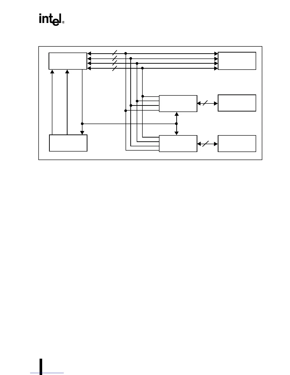
Figure 4-6. Data Bus Interface to 16- and 8-Bit Memories
4.1.4 Dynamic Bus Sizing During Cache Line Fills
BS8# and BS16# can be driven during cache line fills. The Intel486 processor generates enough
8- or 16-bit cycles to fill the cache line. This can be up to sixteen 8-bit cycles.
The external system should assume that all byte enables are asserted for the first cycle of a cache
line fill. The Intel486 processor generates proper byte enables for subsequent cycles in the line
fill. Table 4-6 shows the appropriate A0 (BLE#), A1 and BHE# for the various combinations of
the Intel486 processor byte enables on both the first and subsequent cycles of the cache line fill.
The “
†
” marks all combinations of byte enables that are generated by the Intel486 processor dur-
ing a cache line fill.
Intel486™
Processor
BS16#
BS8#
Address
Decode
32-Bit
Memory
16-Bit Memory
8-Bit Memory
Byte Swap
Logic
Byte Swap
Logic
16
8
8
8
8
8
D7–D0
D15–D8
D23–D16
D31–D24
(A31–A2, BE3#–BE0#)