7-37
PERIPHERAL SUBSYSTEM
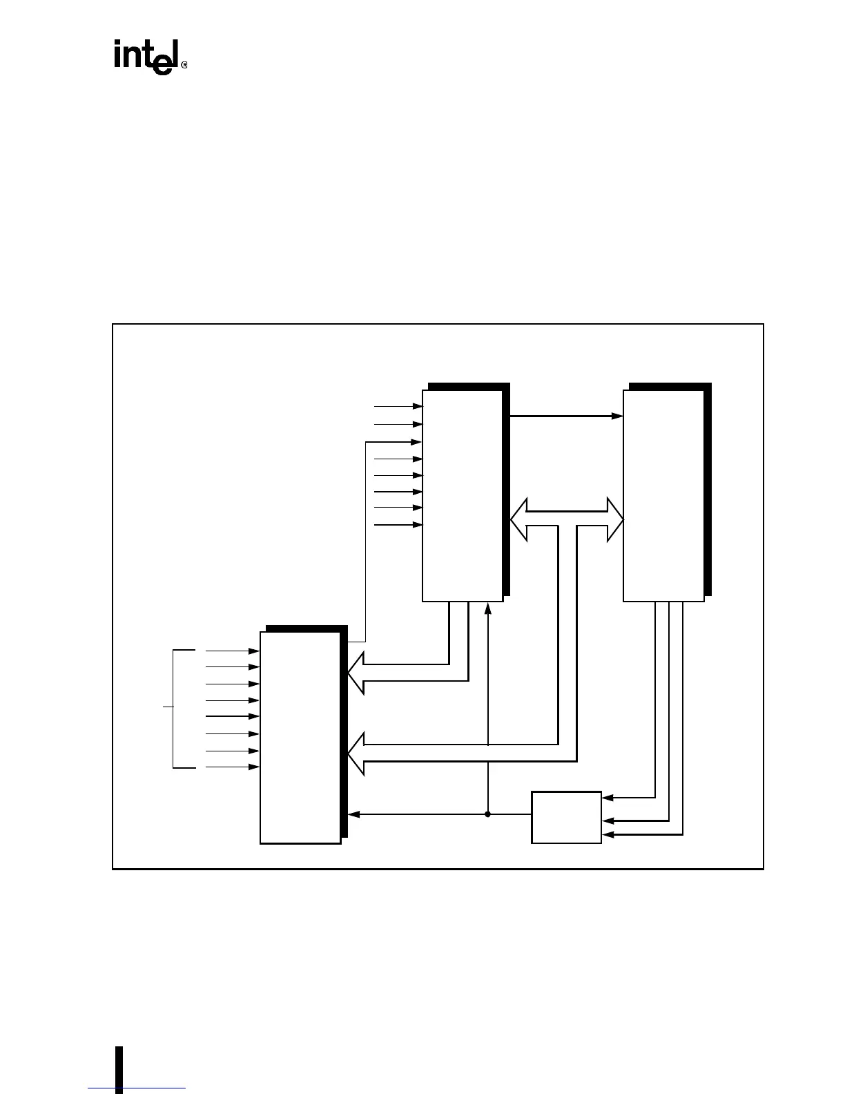
7.5.2.2 Cascaded Interrupt Controllers
Figure 7-20 shows how several interrupt controllers can be cascaded to handle up to 64 interrupt
requests. One device acts as the master and the rest as slaves. The interface between these devices
resembles the single device interface with the following additional features:
• The cascaded address outputs are used to provide address and chip select signals for the
slave controllers.
• The interrupt request lines (IR7–IR0) of the master controller are connected to the INTR
outputs of the slave devices.
Figure 7-20. Cascaded Interrupt Controller
The function of each slave controller is to identify the priorities among eight interrupt requests
and generate a single interrupt request for the master controller. The master controller must iden-
tify the priorities among eight slave controllers and transmit a single interrupt request to the
Intel486 processor.
Master 82C59A
Programmable
Interrupt Controller
Intel486™ Processor
INTRINTR
IRQ0
IRQ1
IRQ2
IRQ3
IRQ4
IRQ5
IRQ6
IRQ7
Slave 82C59A
Programmable
Interrupt Controller
INTR
IRQ0
IRQ1
IRQ2
IRQ3
IRQ4
IRQ5
IRQ6
IRQ7
Cascade Bus
D7:D0
INTA#
Bus Cycle
Type
Decoder
M/IO#, D/C#, W/R#
IRQ14
IRQ15
IRQ8
IRQ9
IRQ10
IRQ11
IRQ12
IRQ13
IRQ6
IRQ7
IRQ0
IRQ1
IRQ2
IRQ3
IRQ4
IRQ5
From ISA
Slots
PLOCK#
LOCK#
INTA#