EMBEDDED Intel486™ PROCESSOR HARDWARE REFERENCE MANUAL
7-14
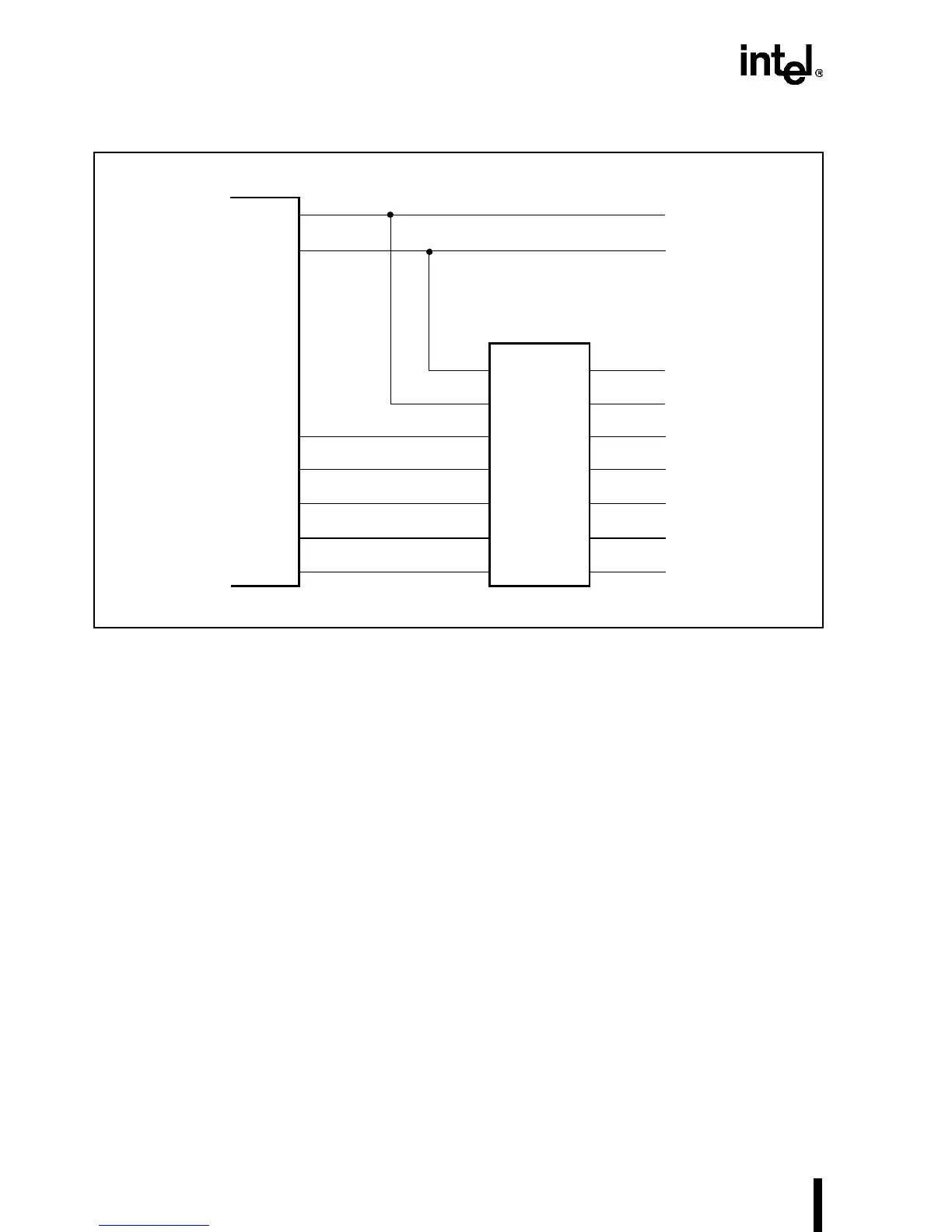
Figure 7-6. Bus Swapping and Low Address Bit Generating Control Logic
7.1.3.4 32-Bit I/O Interface
A simple 32-bit I/O interface is shown in Figure 7-7. The example uses only four 8-bit wide bi-
directional buffers which are enabled by BE3#–BE0#. Table 7-2 provides different combinations
of BE3#–BE0#. To provide greater flexibility in I/O interface implementation, the design should
include interfaces for 32-, 16- and 8-bit devices. The truth table for a 32-to-32-bit interface is
shown in Table 7-10.
PLD
BS8#
BS16#
BS0#
BS1#
BS2#
BS3#
ADS
From 8-Bit
From 16-Bit
BEN16#
BEN8UH#
BEN8UL#
BEN8H#
A0
A1
BHE#