EMBEDDED Intel486™ PROCESSOR HARDWARE REFERENCE MANUAL
10-38
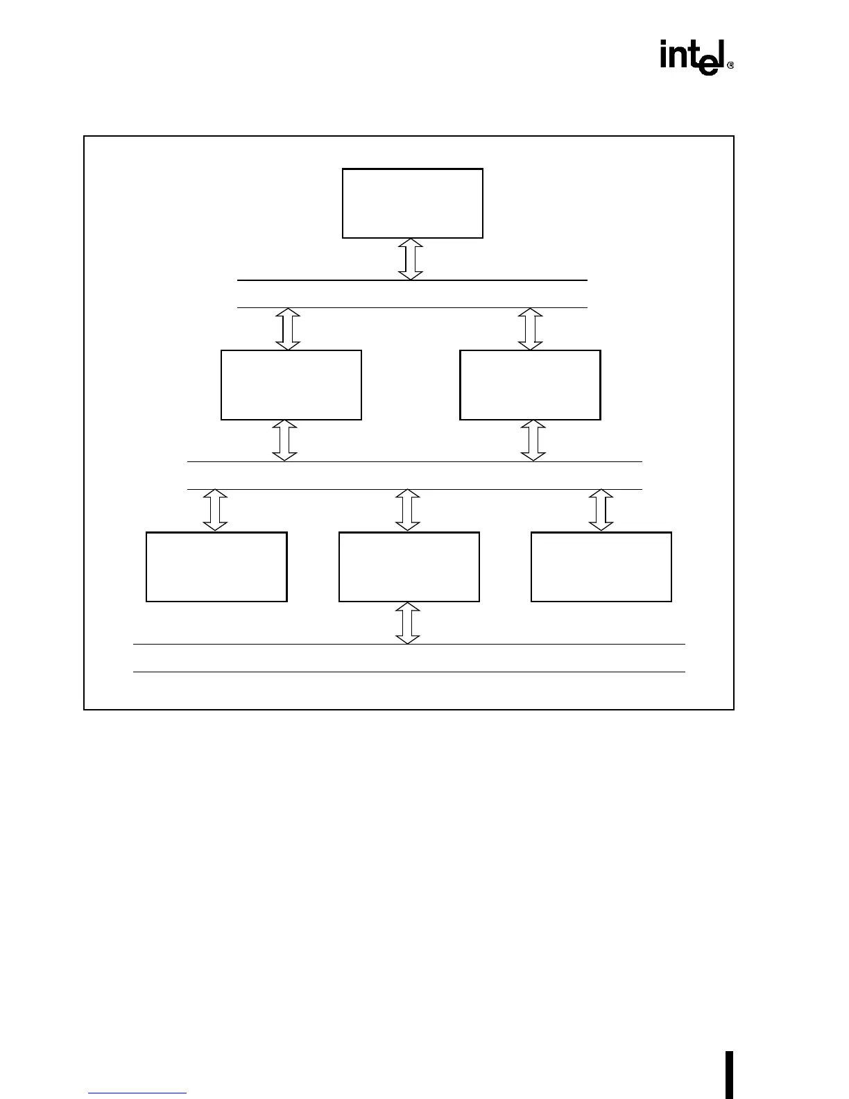
Figure 10-30. Typical Intel486™ Processor-Based System
An optional second-level cache can also be added to the system. The following steps are usually
carried out in designing with the Intel486 processor.
1. Clock circuitry should consist of an oscillator and fast buffer. The CLK signal should be
clean, without any overshoot or undershoot.
2. The reset circuitry should be designed as shown in Chapter 4, “Bus Operation.” This
circuitry is used to generate the RESET # signal for the Intel486 processor. The system
should be checked during reset for all of the timings. The clock continues to run during
these tests.
3. The INT and HOLD pins should be held low (deasserted). The READY# pin is held high
to add additional delays (wait states) to the first cycle. At this instance, the Intel486
processor is reset, and the signals emitted from it are checked for the validity of the state.
Intel486™
Processor
Processor Bus
System Bus
External Bus
Memory Bus Controller
LAN
Coprocessor
Bus
Controller
External
Cache
(Optional)