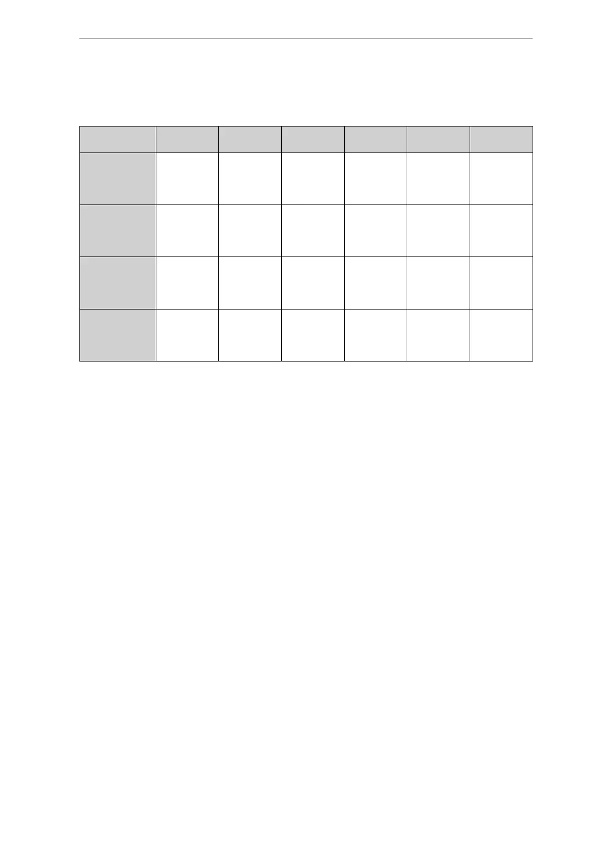
Table 29 shows CMO VSD cylinder unloading configuration with the Centa coupling. Percen-
tages shown are the capacity at maximum speed.
Cylinders 2 3 4 5 6 8
Compressor
CMO/HPO 24
Digital output DO10 DO11
100%
1
DO12
CMO/HPO 26
Digital output -
50%
2
DO10 DO11
100%
1+2
DO12
CMO/HPO 28
Digital output -
50%
2
DO10
TPV (1)
DO11
100%
1+2
+DO12
TCMO 28
Digital output -
33%
2
DO09 DO10 DO11
100%
1+2
+DO12
Table 29: CMO VSD cylinder unloading configuration with Centa coupling
The digital output and solenoid valves which must be activated to provide capacity control are
emphasised with bold letters.
The thermo pump TPV connection for the high cylinder part is also shown in Table 29. The
TPV connection has not been changed - it is the same as for the standard compressor.
The thermo pump high cylinder part step is however only mechanically available for CMO/HPO
28. VSD Total unloading will at first not be mechanically available for CMO/HPO/TCMO.
*) Note that with VSD unloading, output DO09 will correspond to 33% (2+2 cylinders) as for
a standard TCMO 28.
Compressor control and surveillance
122/319
Engineering manual - Unisab III 1.10
001930 en 2014.09
 Loading...


