4. Loosen the capve screws on the front faceplate of the expansion module by using your ngers. If
you are unable to loosen the capve screws by using your ngers, use the screwdriver.
5. Using both hands, place the expansion module in the empty slot and slide it in gently unl it is fully
seated.
NOTE: Aer you have removed an expansion module, wait for at least 5 seconds before you
install an expansion module. If you do not wait for at least 5 seconds, the interfaces on the
expansion module might not come up.
6. Raise the handle and ghten the capve screws by using your ngers or the screwdriver. When the
ST LED turns green, the expansion module is ready for use.
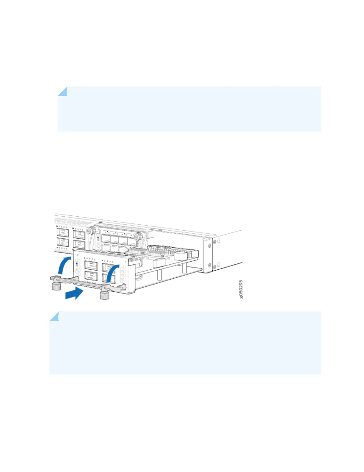
Figure 43 on page 105 shows how to install a QSFP+ expansion module on the port panel of a EX4600
switch.
Figure 43: Installing a QFX4Q Expansion Module in an EX4600 Switch
NOTE: If you have a Juniper Care service contract, register any addion, change, or upgrade of
hardware components at hps://www.juniper.net/customers/support/tools/updateinstallbase/ .
Failure to do so can result in signicant delays if you need replacement parts. This note applies if
you change the type of power supply or add a new type of expansion module. It does not apply if
you replace these components with the same type of component.
105