6. Engine Removal;In
spection & Installation
6-42
1
Hexagon flange bolts 14*26 7 Hexagon flange bolts M8*32
2
Shift positioning spring 8 driven shaft
3
Shift positioning steel balls 9 countershaft
4
O-ringΦ2*Φ10 10 Shift drum assembly
(see Z-05
explain)
5
drive shaft 11 water seal
6
reverse gear shaft 12 oil sealΦ12*25*7
(see Z-06 water se
seal tha
t split)
7.1
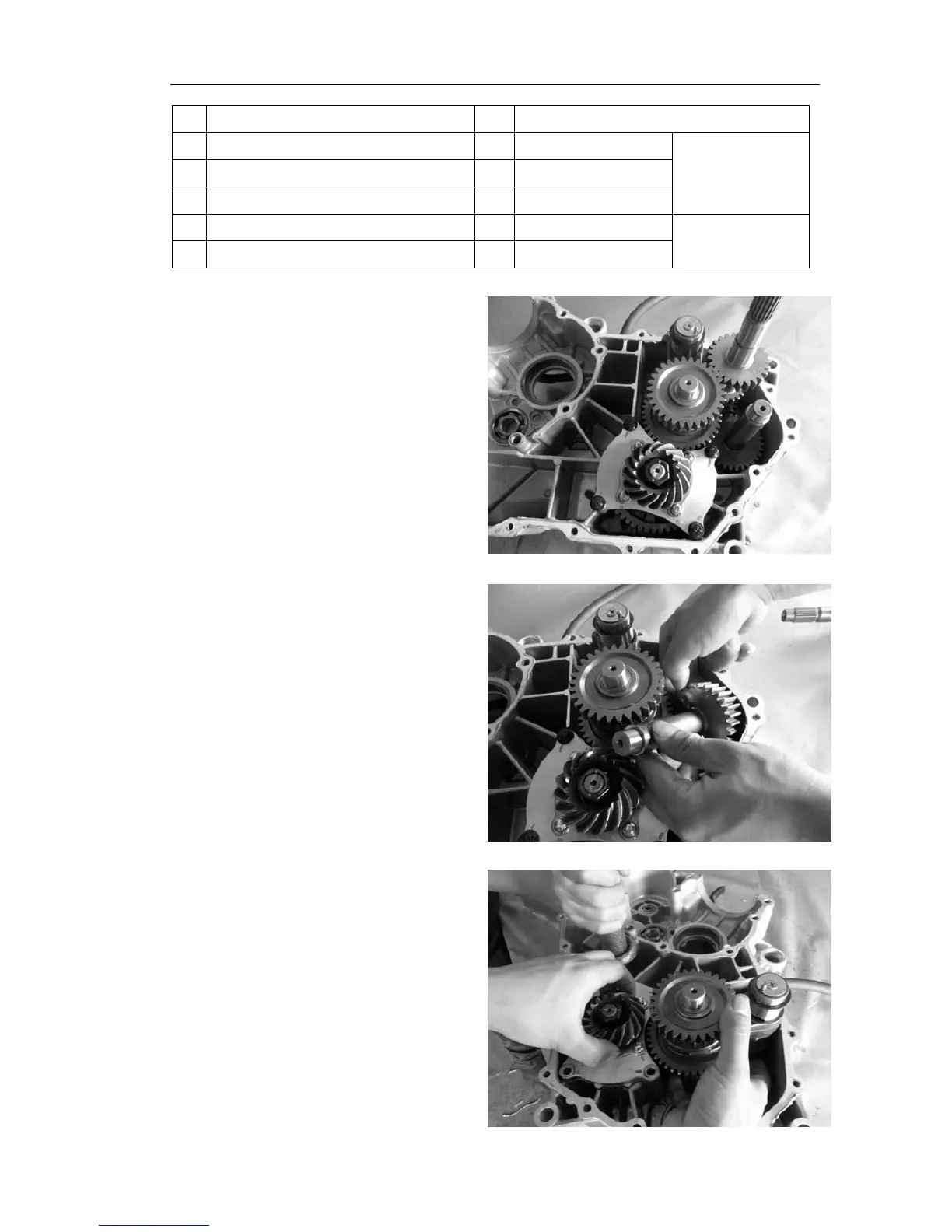
As shown in figure the drive shaft remove,
directly from the right by hand on it out.
7.2 As shown in figure reverse gear shaft removal,
the reverse axial driven shaft direction tilt,
hands caught in reverse axis tilt out tooth surface.
7.3 As shown in figure driven shaft, deputy
shaft and shift drum remove, a hand grasp
on the driven shaft components active bevel
gear, and the other a hand grasp vice axis
and shift drum, gently in the copper with
right to strengthen place stroke, make three
components from the right out the cabinet.