6. Engine Removal;In
spection & Installation
6-14
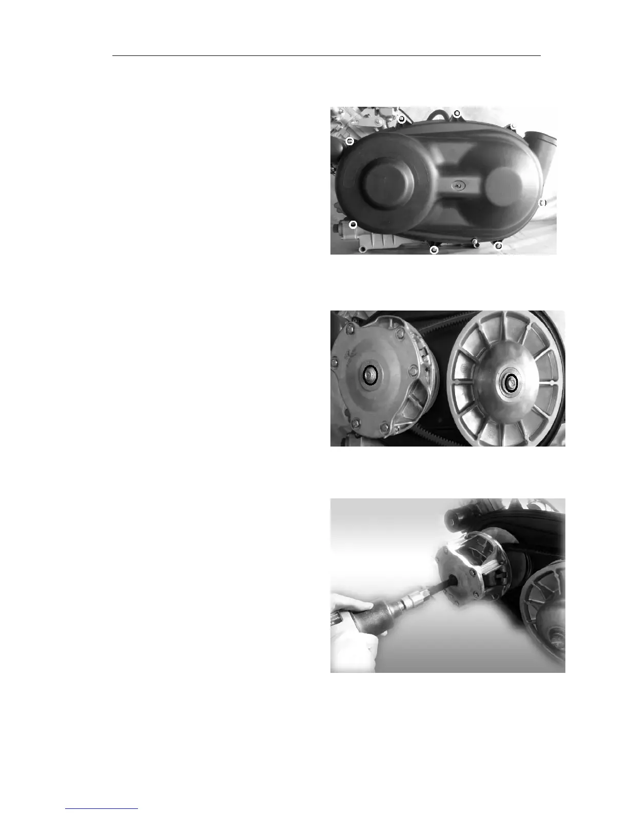
1.1 As shown in figure rem
ove left
upper lid hex flange bolts
1.2 As shown in figure remove CVT
active wheel and driven wheels on
the flange bolts
1.3 Remove the CVT active wheel as
shown in figure:
1.3.1 With specialized tools twist
intothe CVT active wheel sliding
shaft inside, with pneumatic
board tightened the specialized
tools, will be active round out the
top. Note: 1. A special tool to
twist in place, in order to avoid
sliding axis will be threaded damage.