3-10 Basic DMM Operation Model 2701 User’s Manual
Model 7700 switching module
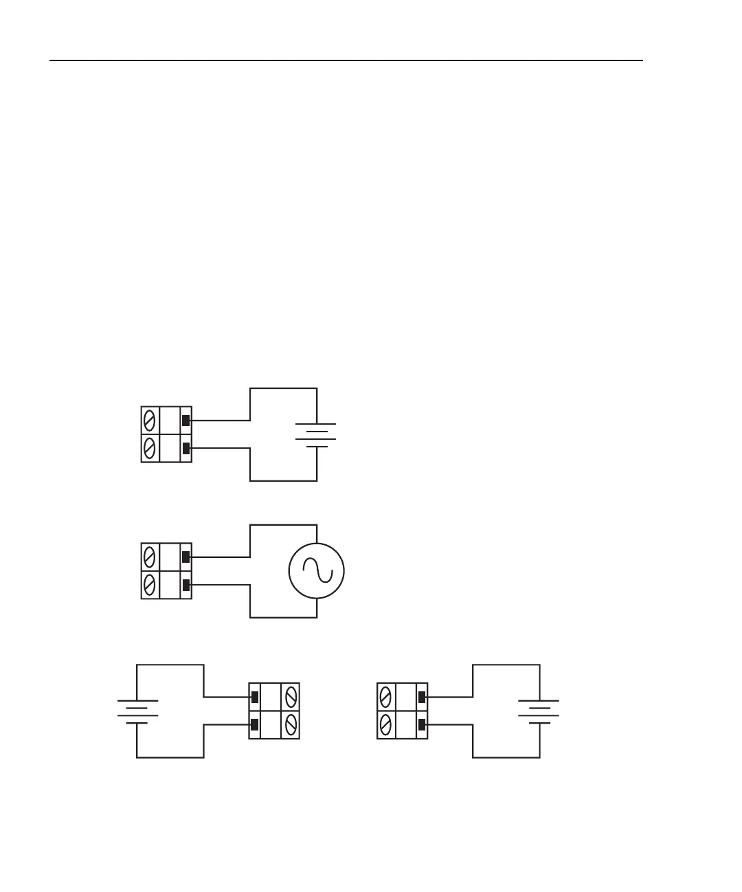
Connections for the Model 7700 switching module are shown in Figure 3-3. For basic
DCV and ACV measurements (Figure 3-3A and B), channels 1 through 20 can be used.
Ratio and channel average calculations — Ratio calculates the reading ratio of two
channels, while channel average calculates the reading average of two channels. For these
calculations, paired switching channels are used. Primary channels 1 through 10 are paired
to channels 11 through 20 (channel 1 paired to channel 11, channel 2 paired to channel 12,
and so on). As shown in Figure 3-3C, one DC voltage source is connected to a primary
channel (i.e., 104) and the other source is connected to its paired channel (i.e., 114).
NOTE The ratio and channel average calculations are covered in Section 5.
Figure 3-3
DCV and ACV connections using Model 7700 switching module
AC Voltage
Source
H
L
CH 1-20
Model 7700
Switching
Module
DC Voltage
Source
H
L
CH 11-20
DC
Voltage
Source
A. DCV Connections
B. ACV Connections
C. Ratio and Channel Average Connections (DCV)
Caution: Maximum input: 300VDC or RMS, 1A switched,
60W, 125VA maximum
Note: The low connections for channels 1 through 10 do not
need to be referenced to the low connections for
channels 11 through 20.
H
L
CH 1-20
Model 7700
Switching
Module
H
L
CH 1-10
Model 7700
Switching
Module
DC
Voltage
Source