Model 2701 User’s Manual Measurement Considerations E-3
Thermoelectric generation
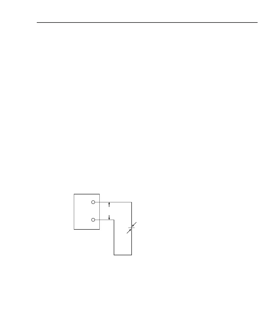
Figure E-1 shows a representation of how thermal EMFs are generated. The test leads are
made of the A material, while the source under test is the B material. The temperatures
between the junctions are shown as T
1
and T
2
. To determine the thermal EMF generated,
the following relationship may be used:
E
T
= Q
AB
(T
1
– T
2
)
where: E
T
= Generated thermal EMF
Q
AB
= Thermoelectric coefficient of material A with respect to material B (µV/°C)
T
1
= Temperature of B junction (°C or K)
T
2
= Temperature of A junction (°C or K)
In the unlikely event that the two junction temperatures are identical, no thermal EMFs
will be generated. More often, the two junction temperatures will differ and considerable
thermal EMFs will be generated.
A typical test setup will probably have several copper-to-copper junctions. As pointed out
earlier, each junction can have a thermoelectric coefficient as high as 0.2µV/°C. Since the
two materials will frequently have a several degree temperature differential, it is easy to
see how thermal potentials of several microvolts can be generated even if reasonable
precautions are taken.
Figure E-1
Thermal EMF generation
HI
LO
E
T
= Q
AB
(T
1
– T
2
)
E
T
T
1
T
2
A
B
2182
CH1
2701