Model 2701 User’s Manual Basic DMM Operation 3-49
will not beep and either display the resistance reading or the message “OPEN”. If the
reading is below 1100Ω, it will be displayed. If the reading is 1100Ωor above, “OPEN”
will instead be displayed.
NOTE The reading rate for continuity is fixed at 0.01 PLC.
Limits and digital outputs cannot be used when testing continuity with the conti-
nuity (CONT) function. If you need to use these operations, use the
Ω
2 function
to test continuity.
Connections
NOTE When using the front panel inputs, the INPUTS switch must be in the “F” (out)
position. For switching modules, it must be in the “R” (in) position.
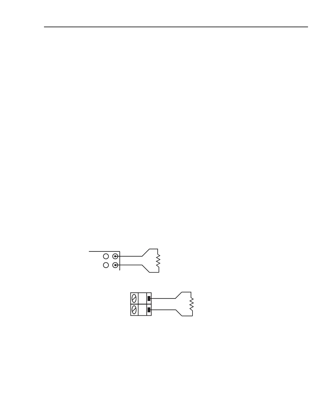
Front panel input
When using the front panel input terminals, connect the test leads to the INPUT HI and
LO terminals as shown in Figure 3-19A.
Model 7700 switching module
Connections for the Model 7700 switching module are shown in Figure 3-19B. Since this
is a 2-wire ohms measurement, channels 1 through 20 can be used.
Figure 3-19
Continuity connections
H
L
CH 1-20
Model 7700
Switching
Module
Resistance
Under Test
Note: Source current flows from input high to input low.
Model 2701
Input HI
Input LO
Resistance
Under Test
A. Front panel connections
B. Model 7700 connections