Model 2701 User’s Manual Basic DMM Operation 3-47
Connections
NOTE When using the front panel inputs, the INPUTS switch must be in the “F” (out)
position. For switching modules, it must be in the “R” (in) position.
Front panel input
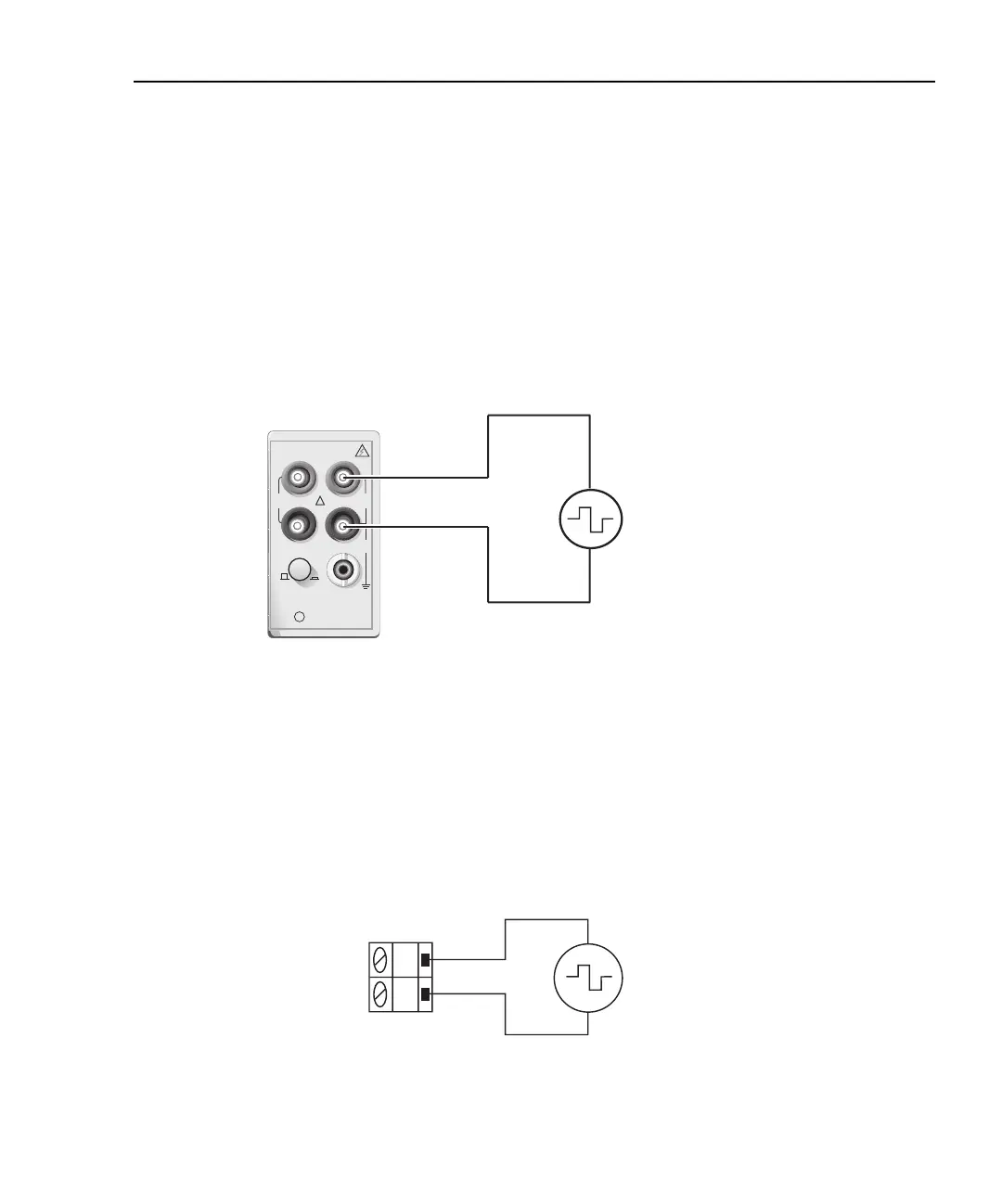
When using the front panel input terminals, connect the test leads to the INPUT HI and
LO terminals as shown in Figure 3-17.
Figure 3-17
FREQ and PERIOD connections for front panel inputs
Model 7700 switching module
Connections for the Model 7700 switching module are shown in Figure 3-18. For this
2-wire measurement, channels 1 through 20 can be used.
Figure 3-18
FREQ and PERIOD connections using Model 7700 switching module
Input Impedance = 1MΩ in parallel with <100pF
Caution: Maximum Input = 1000V peak, 8 x 10
7
V•Hz
Model 2701
AC Voltage
Source
!
F
500V
PEAK
FRONT/REAR
3A 250V
AMPS
HI
INPUT
LO
SENSE
Ω4 WIRE
INPUTS
350V
PEAK
1000V
PEAK
R
CAT I
H
L
CH 1-20
Model 7700
Switching
Module
AC
Voltage
Source
Caution: Maximum = 300V peak or RMS, 8 x 10
7
V•Hz