9-16 Limits and Digital I/O Model 2701 User’s Manual
The limits are illustrated in Figure 9-7.
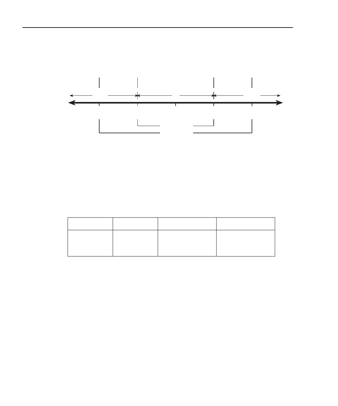
Figure 9-7
Limits to sort 100Ω resistors (1%, 5%, and >5%)
Front Panel Operation — For front panel operation, the INSIDE beeper mode must be
used. A normal pitch beep and the message IN indicates that the resistor is within the 1%
tolerance limit (Figure 9-7). This 1% resistor belongs in Bin 1. A raspy beep and the “1”
message indicates that the resistor is >1% tolerance but <5% tolerance. This 5% resistor
belongs in Bin 2. For resistors >5%, no beep will sound. Place these resistors in Bin 3.
Remote Operation — For remote operation, make sure both Limit 1 and Limit 2 are
enabled. The following table evaluates the three possible pass/fail combinations for this
example.
Keep in mind that a fail condition must be reset before testing the next resistor. Fail can be
reset manually or automatically (see Table 9-2, CLEar command).
Limit 1 result Limit 2 result Resistor tolerance Bin assignment
Pass Pass >1% 1
Fail Pass >5% 2
Fail Fail >5% 3
100W 101W
HI1
105W
HI2
95W
LO2
99W
LO1
Limit 1 (1%)
Limit 2 (5%)
LOW IN
HIGH
Beep
(normal pitch)
Beep
(low pitch)
Beep
(low pitch)
No Beep
No Beep