10-10 Remote Operations Model 2701 User’s Manual
Ethernet connections
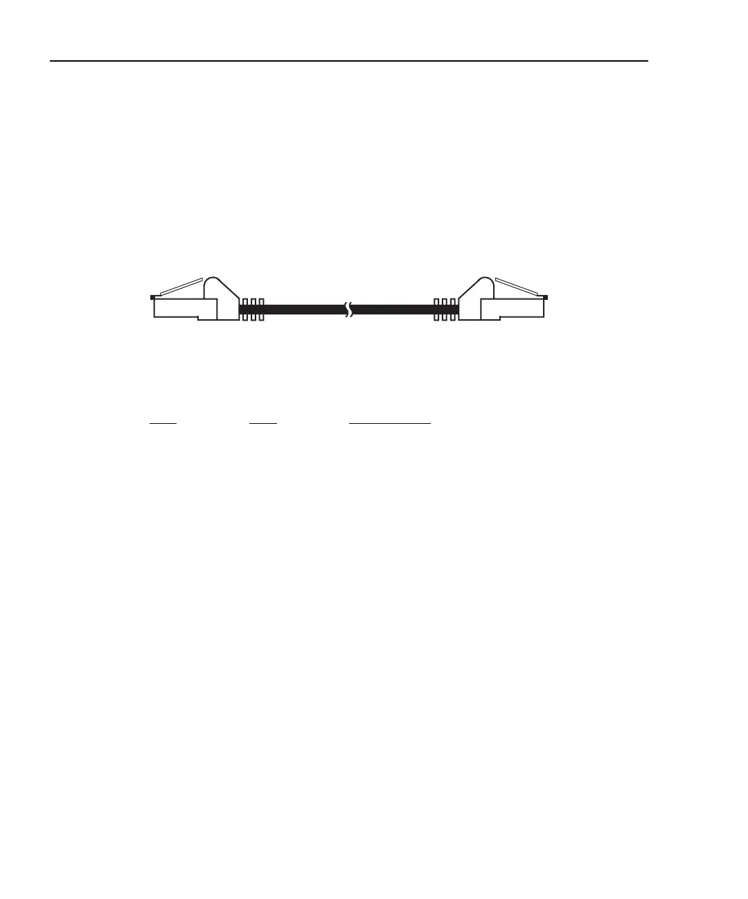
The Model 2701 is connected to the Ethernet using a male-to-male RJ-45 Ethernet cable
(see Figure 10-5). The Ethernet connector for the Model 2701 is shown in Figure 10-6.
With power off, connect one end of the cable to the Model 2701 and connect the other end
to the Ethernet connector of the PC, hub, or receptacle.
Figure 10-5
RJ-45 Ethernet cable (male/male)
RJ-45 connector status LEDs
The female RJ-45 connector (shown in Figure 10-6) has two status LEDs located at the
top of the connector. These LEDs provide the following status:
LED State Ethernet status
10bT On Network connected (10 mb/s connection)
10bT Blinking Traffic is traversing the port (10 mb/s connection)
10bT Off 10 mb/s network is NOT connected
100bT On Network connected (100 mb/s connection)
100bT Blinking Traffic is traversing the port (100 mb/s connection)
100bT Off 100 mb/s network is NOT connected
Ethernet Cable
RJ-45 male-to-male