Model 2701 User’s Manual Limits and Digital I/O 9-15
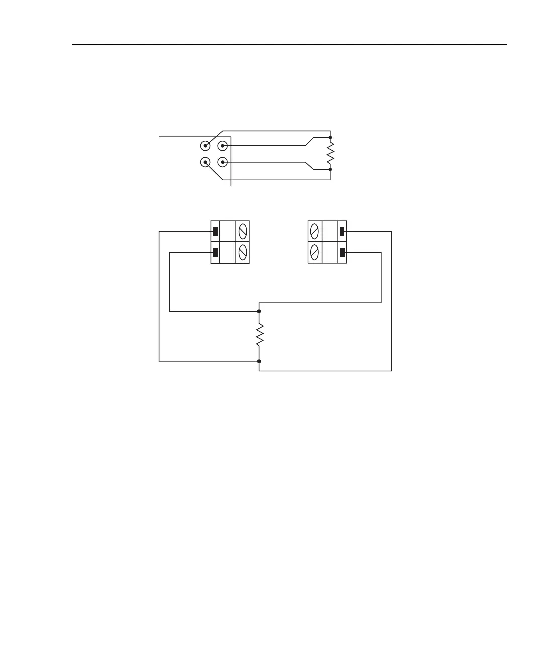
Figure 9-6
Setup to test 100Ω resistors
Limit 1 will be used to test for the 1% tolerance and Limit 2 will be used to test for the 5%
tolerance.
The resistance values for the 1% and 5% tolerances are calculated as follows:
R
1%
= 100Ω × 1% R
5%
= 100Ω × 5%
= 100Ω × 0.01 = 100Ω × 0.05
= 1Ω = 5Ω
The high and low limits are then calculated as follows:
HI Limit 1 = 100Ω + R
1%
HI Limit 2 = 100Ω + R
5%
= 100Ω + 1Ω = 100Ω + 5Ω
= 101Ω = 105Ω
LO Limit 1 = 100Ω – R
1%
LO Limit 2 = 100Ω – R
5%
= 100Ω – 1Ω = 100Ω – 5Ω
= 99Ω = 95Ω
H
L
CH 1-10
Model 7700
Switching
Module
H
L
CH 11-20
B) Model 7700
INPUT
SENSE
Model 2701
Input HI
Input LO
Sense HI
Sense LO
A) Front panel inputs
100Ω
100Ω