9-10 Limits and Digital I/O Model 2701 User’s Manual
Source mode — logic control
The digital outputs can be used as logic inputs to active TTL, low-power TTL, or CMOS
inputs. For this mode of operation, the output lines can source up to 200µA.
CAUTION Each output line can source up to 200µA. Exceeding 200µA may cause
damage to Model 2701 that is not covered by the warranty.
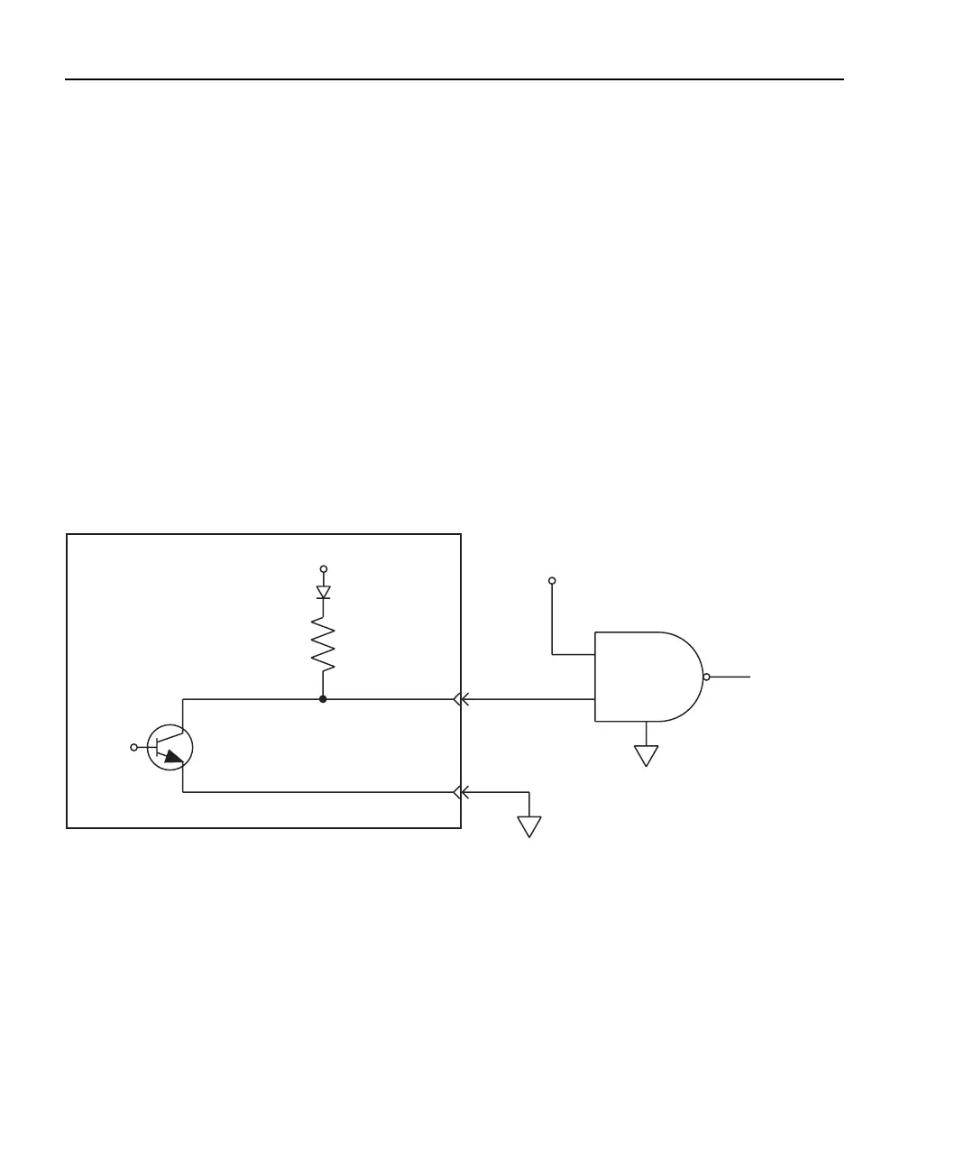
Figure 9-5 shows how to connect a logic device to one of the output lines. When the output
line is pulled high, the transistor will turn off (transistor switch open) to provide a reliable
logic high output (>3.75V). When the output line goes low, the transistor turns on
(transistor switch closed) to route current to digital ground. As a result, a low logic output
(0V) is provided at the output.
If the second input (B) of the NAND gate is connected to another output line of the port,
the output of the NAND gate will go to logic 0 when both digital outputs are set high.
Figure 9-5
NAND gate control
Setting digital output
The OUTPUT menu (shown in Table 9-1) is used to control and configure digital outputs.
Menu items for the digital output include:
• DOUTPUT — Use to enable (ON) or disable (OFF) the digital outputs.
• PULSE — Use to enable (YES) or disable (NO) the pulse option for the digital
outputs.
NOTE The factory default pulse time is 2ms maximum. Using remote programming,
pulse time can be set from 0.001 to 99999.999 sec. It cannot be set from the front
panel.
Model 2701
4.75kW
Pull Up Resistor
Pin 9
Digital
Output
Logic Device
NAND
B
A
Control
Line
+5V