3 Replacing Assemblies
194 Keysight 53210A/53220A/53230A Assembly Level Service Guide
To Remove the Front Panel Assembly
1 Remove the cover and rear bezel from the counter as described previously.
2 If installed, remove the Option 300 Internal DC Battery assembly as described
previously.
3 If installed, remove the GPIB assembly as described previously.
4 If installed, remove the Option 106 or 115 Microwave Channel assembly as
described previously.
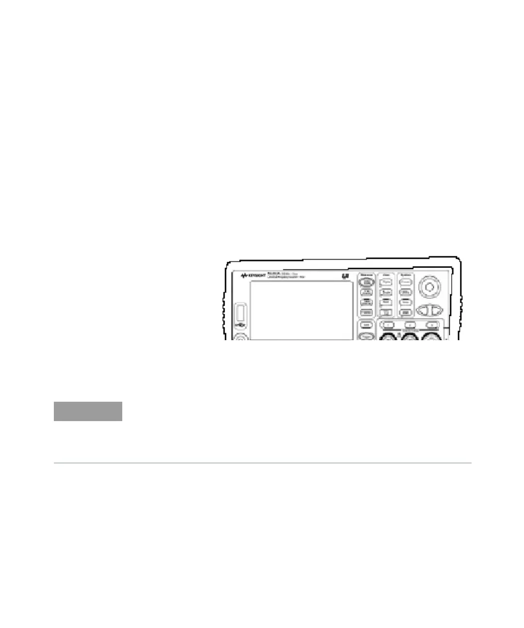
5 To remove the front rubber bumper, stretch a corner and then slide it off as
shown in Figure 3-7.
Figure 3-7 Front rubber bumper removal
6 Remove the front panel assembly as follows:
7 Turn the chassis upside down. Remove the smaller processor board from the
motherboard as described previously (see Figure 3-6).
8 Remove the board carefully from its edge connector and set it aside in a safe
location on the ESD mat.
Read each instruction step in its entirety, while examining the hardware and
referring to the appropriate figure(s), before proceeding with the step. This will
acquaint you completely, in advance, with the action to be performed. The
actions in some steps must be accomplished simultaneously to succeed. Read
all nearby NOTES carefully.