Retrofitting Options 4
Keysight 53210A/53220A/53230A Assembly Level Service Guide 221
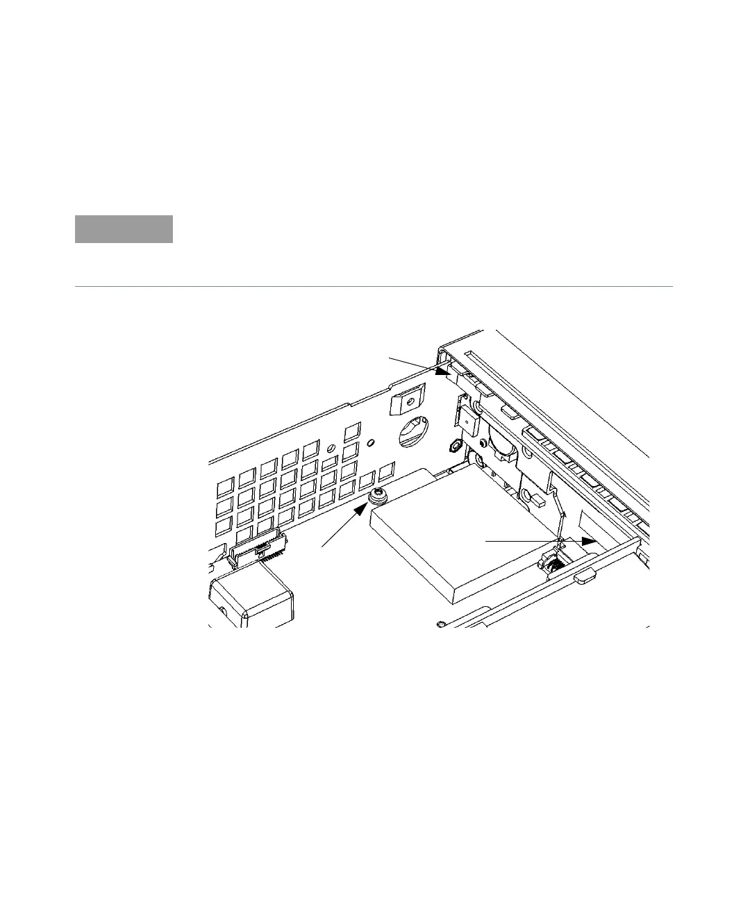
5 Turn the counter chassis upright and position the counter as shown in
Figure 4-10.
6 Remove the T20 TORX screw on the front left-hand side of the motherboard
as shown in Figure 4-10.
Figure 4-10 T20 TORX screw on motherboard
7 With your right hand, press in on the plastic tab (X on Figure 4-10) at the top
left front of the front panel, while at the same time, use your left hand to
press in on the front of the left-hand aluminum chassis side-panel, so that
the front of the side-panel overlaps the depressed tab and keeps it
depressed. The left front standoffs should now be free of their holes.
The four standoffs on the aluminum side panels (two on each side, front) secure
the front panel into the four holes cut out on the plastic sides of the front panel
(two on each side). The next steps free the standoffs from the holes so the front
panel can be removed.