1 Performance Tests
72 Keysight 53210A/53220A/53230A Assembly Level Service Guide
Counter setup
1 Press the Preset key to preset the counter.
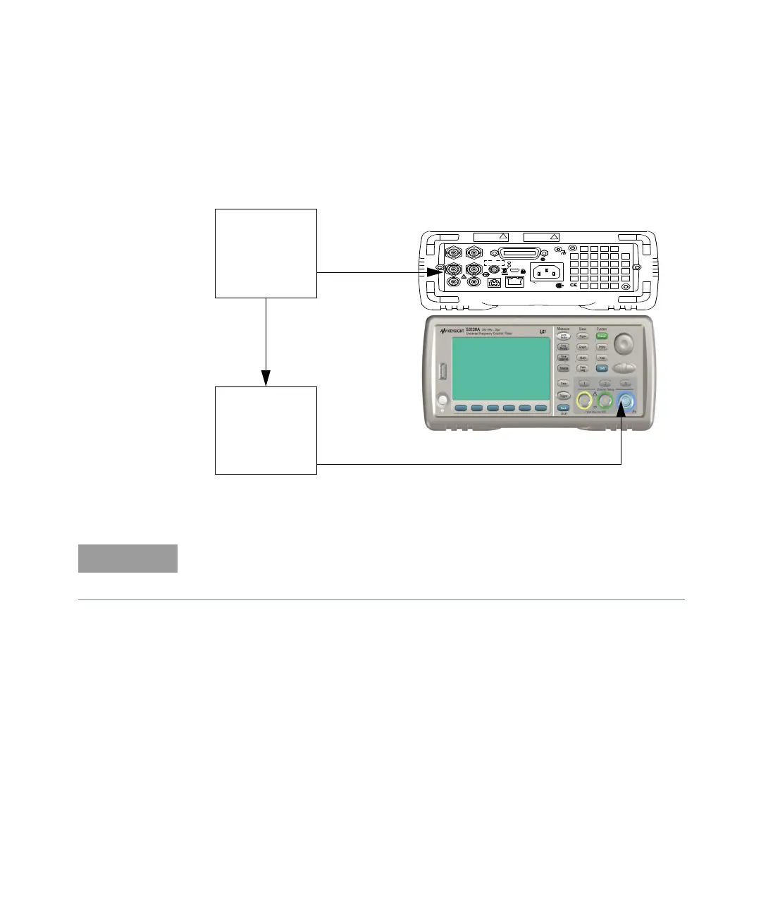
2 Connect the equipment as shown in Figure 1-9.
Figure 1-9 Option 115 ( 15 GHz ) microwave channel 2/3 test setup
Opt 010 UOCXO
Lin e
100-240V, 50-60 Hz
100-127V, 400 Hz
90VA M ax
U S B L A N
In t R e f O ut Trig In
E xt R ef In G ate I n /O ut
Ch 1 O pt 20 1 C h 2 G P-IB
Opt 106/115
IECS / NMB-001
N10149
ISM 1-A
C U S
Opt 106
100 MHz - 6 GHz
+27 dBm Max
!
Opt 300 B attery
Opt 115
300 MH z - 15 GHz
+27 dBm Max
!
FS725
Rubidium
Timebase
Ext Ref In
E8257D-520
Microwave
Signal
Generator
Ch 2/3
For the Keysight 53210A Counter, Option 115 is installed as Channel 2. For the
Keysight 53220A and 53230A Counters, Option 115 is installed as Channel 3. For
this procedure, “Channel 3” is used to refer to the microwave input channel.