2Service
166 Keysight 53210A/53220A/53230A Assembly Level Service Guide
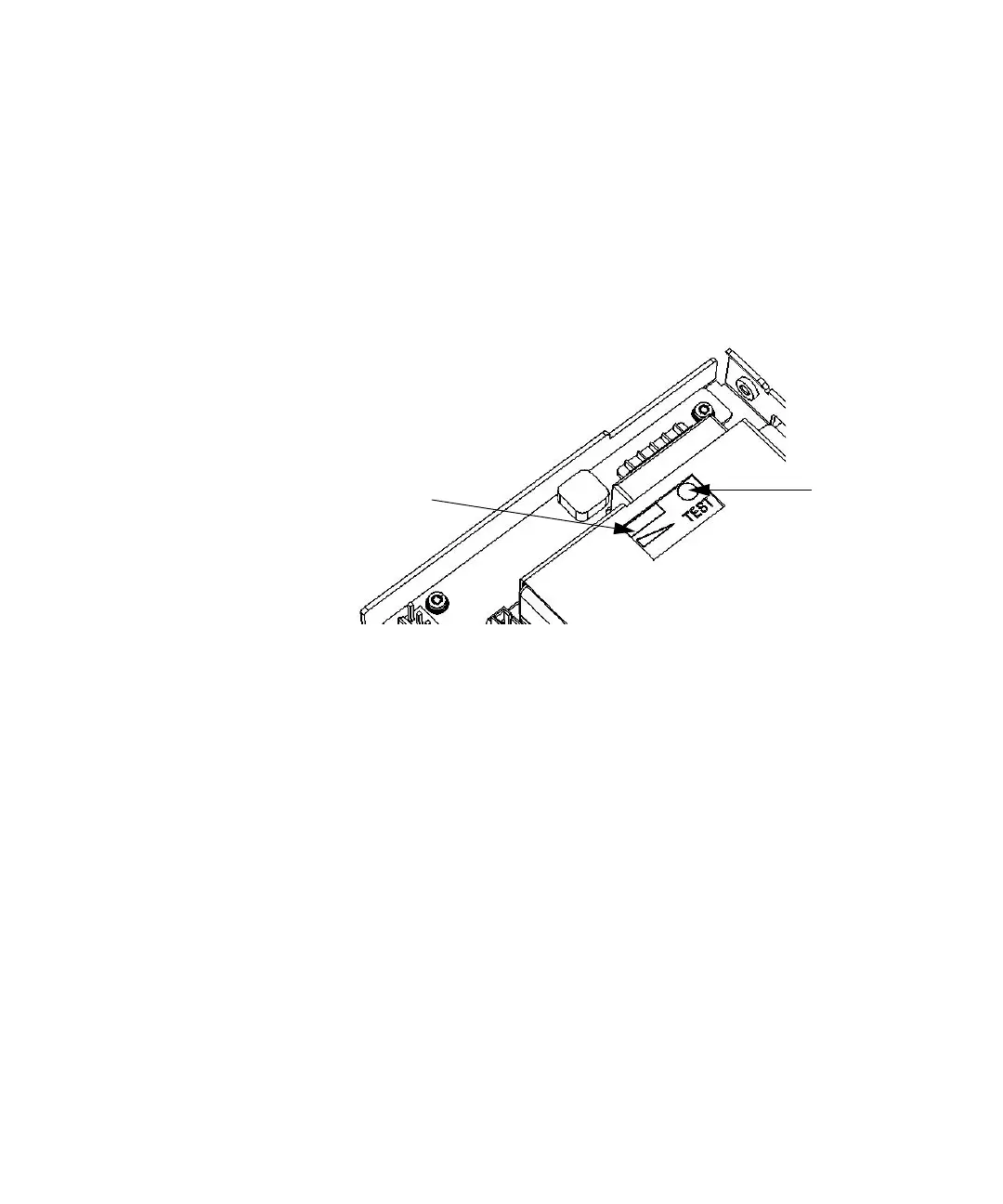
Testing the battery
7 On the Battery assembly, push and hold the white test button on the battery
while observing the charge-level indicator. (See Figure 2-13). The charge level
should be at least 25% to be functional. If the battery has been installed for
over 24 hours with counter AC power connected the entire time, the charge
level should be 75 to 100%. (Typically at least 25% after 1 hour charge.)
Figure 2-13 Test Button and Charge Indicator
8 With counter AC power still disconnected, use a DMM to measure the DC
voltage on the battery charging assembly 8-pin connector (J100, still
connected to the motherboard) from pins 5 & 6 to ground.
– Both pins should read between +10 and +13 VDC.
9 Connect the AC power cord to the counter.
– The Power LED next to the counter Power switch should be off (Standby
mode).
10 Repeat step 8.
– Both pins 5 & 6 should read +15 VDC ± 0.2 VDC.
– Pins 1 & 2 should also read +15 VDC ± 0.2 VDC. (AC Power supply output)
11 If the voltages in step 8 above are missing, or if there is no reading on the
battery charge level indicator in step 7, replace the battery (p/n 1420-0909).