1 Performance Tests
56 Keysight 53210A/53220A/53230A Assembly Level Service Guide
Counter setup
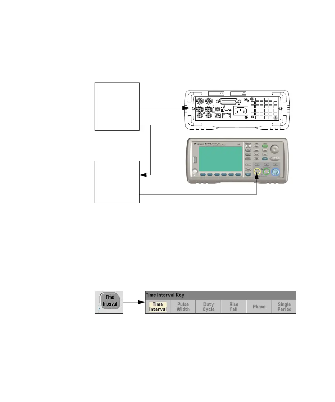
1 Connect the equipment as shown in Figure 1-6.
Figure 1-6 Pulse width test setup
2 Press the Preset key to preset the counter.
– Display shows:
– Instrument has been preset.
– Ext Ref is shown in the upper right-hand corner of the display.
3 Press the Time Interval key.
– The following softkeys are displayed:
Opt 010 UOCXO
Lin e
100-240V, 50-60 Hz
100-127V, 400 Hz
90VA M ax
US B L AN
Int Re f Ou t T rig In
Ex t R ef In Ga te In/O ut
Ch 1 Opt 20 1 Ch 2 GP -IB
Opt 106/115
IECS / NMB-001
N10149
ISM 1-A
C U S
Opt 106
100 MHz - 6 GHz
+27 dBm M ax
!
Opt 300 B attery
Opt 115
300 MHz - 15 GHz
+27 dBm Max
!
FS725
Rubidium
Timebase
Ext Ref In
81134A
Pulse
Generator
Ch 1