Replacing Assemblies 3
Keysight 53210A/53220A/53230A Assembly Level Service Guide 191
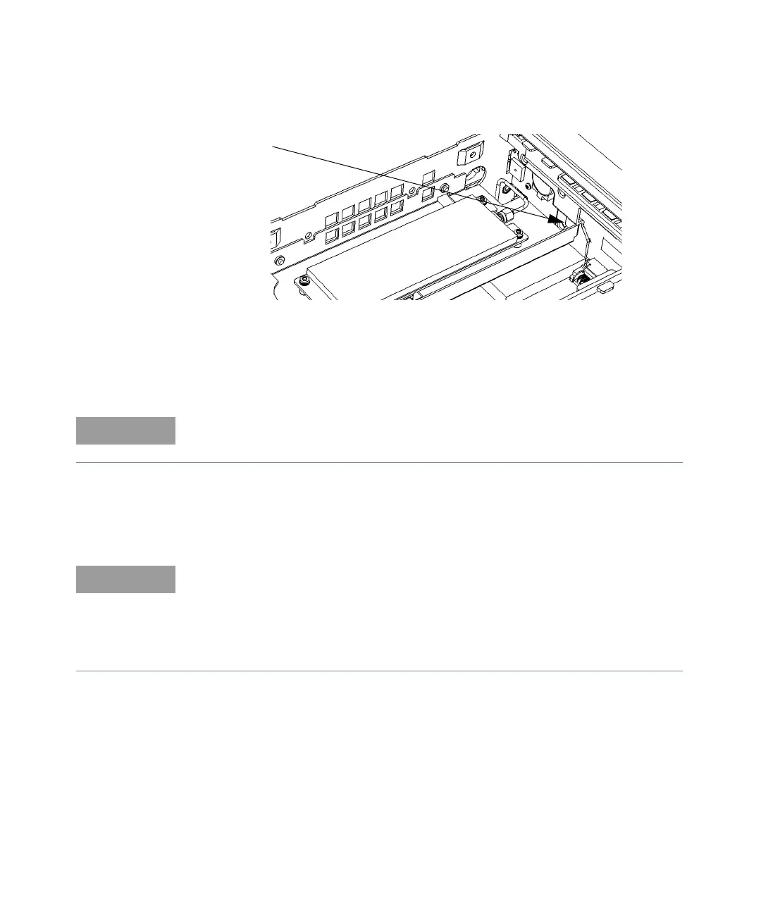
Figure 3-5 Front flange resting on plastic tab
1 Line up the semi-rigid SMA cable male connector and the microwave channel
assmbly SMA female edge connector, connect them together and loosely
tighten the SMA connector.
2 Re-install the T20 TORX screw, securing the rear flange on the microwave
channel bracket to the motherboard. Do not tighten the screw all the way
down at this time.
Front
Flange
Option
106 or
115
Be sure the flange on the front of the assembly remains positioned over the tab
on the front panel assembly.
(Front Panel Input Channel Connector) If the semi-rigid cable connectors do not
line up exactly without distorting the cable, turn the chassis over and, through
the open area provided, use a 5/16" wrench to loosen the SMA connector on the
semi-rigid cable where it connects to the front panel and gently re-position the
cable until it is positioned to connect the assembly to the front panel, with no
stress on either end of the semi-rigid cable.