Retrofitting Options 4
Keysight 53210A/53220A/53230A Assembly Level Service Guide 229
– If Option 115 is being installed, insert and tighten the two supplied
standoffs (using a 1/4" spintite) in the two midd le holes closest to the front
flange of the Channel 2 assembly (Rear Panel Option 203 only).
– Position the printed circuit board over the aluminum bracket so that the
SMA edge connector is pointed toward the rear flange (with the hole in it)
and sits on top of the standoffs.
– Install 4 (Option 106) or 6 (Option 115) T10 TORX screws to secure the
printed circuit board to the aluminum deck.
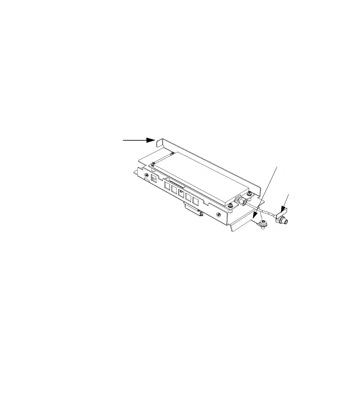
Figure 4-14 53210A channel 2 rear panel Option 106/203
Front
Flange
Rear
Flange
Label