Retrofitting Options 4
Keysight 53210A/53220A/53230A Assembly Level Service Guide 245
Rear panel installation procedure (Option 203 only)
1 Install the Channel 3 assembly as follows:
2 Remove the T20 TORX screw at the rear of the motherboard.
3 Connect one end of the supplied 40-pin ribbon cable to J900 on the
motherboard. Connect the other end to J401 on the underside of the Channel
3 circuit board.
4 Set the Channel 3 assembly down on top of the motherboard so that the
female SMA edge connector is towards the rear panel. The front flange on the
right-front of the Channel 3 assembly bracket must rest on the tab protruding
from the front panel (see Figure 4-22).
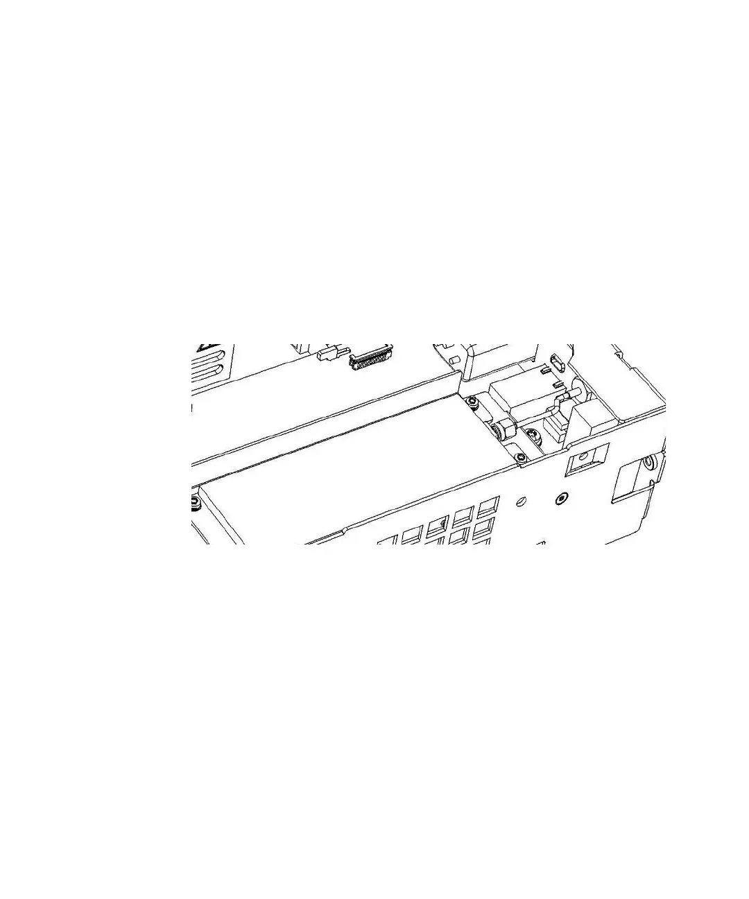
Figure 4-22 Channel 3 assembly installed on top of the motherboard, with
the female SMA edge connector pointing toward the rear.
5 Install the supplied SMA semi-rigid cable as follows:
6 Insert the end of the semi-rigid cable with the female SMA connector through
the hole on the rear panel marked "Opt 106/115". Secure the connector with
the supplied 5/16" hex nut and lockwasher. Finger-tighten only.
7 Line up the male SMA cable connector on the semi-rigid cable and the
Channel 3 assembly female SMA edge connector, connect them together and
tighten both of the SMA connectors using a 5/16" wrench.