1 Performance Tests
84 Keysight 53210A/53220A/53230A Assembly Level Service Guide
Counter setup
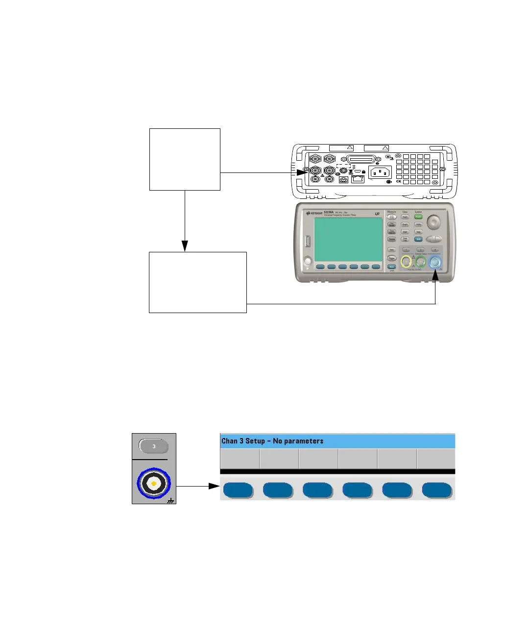
1 Connect the equipment as shown in Figure 1-11.
Figure 1-11 Option 115/150 microwave channel 3 test setup
2 Press the Preset key to preset the counter.
3 If needed, perform an auto-calibration. (Refer to “Internal auto-calibration” on
page 27.)
4 Press the Channel 3 input key.
– Channel 3 is selected for test input.
Opt 010 UOCXO
Lin e
100-240V, 50-60 Hz
100-127V, 400 Hz
90VA M ax
U S B L A N
In t R e f O ut Trig In
E xt R ef In G ate I n /O ut
Ch 1 O pt 20 1 C h 2 G P-IB
Opt 106/115
IECS / NMB-001
N10149
ISM 1-A
C U S
Opt 106
100 MHz - 6 GHz
+27 dBm Max
!
Opt 300 B attery
Opt 115
300 MH z - 15 GHz
+27 dBm Max
!
FS725
Rubidium
Timebase
Ext Ref In
E8257D-520-UNW
Microwave
Signal
Generator
Ch 3