4 Retrofitting Options
208 Keysight 53210A/53220A/53230A Assembly Level Service Guide
4 Slide the outside cover of the counter to the rear and remove the cover.
Battery assembly installation procedure
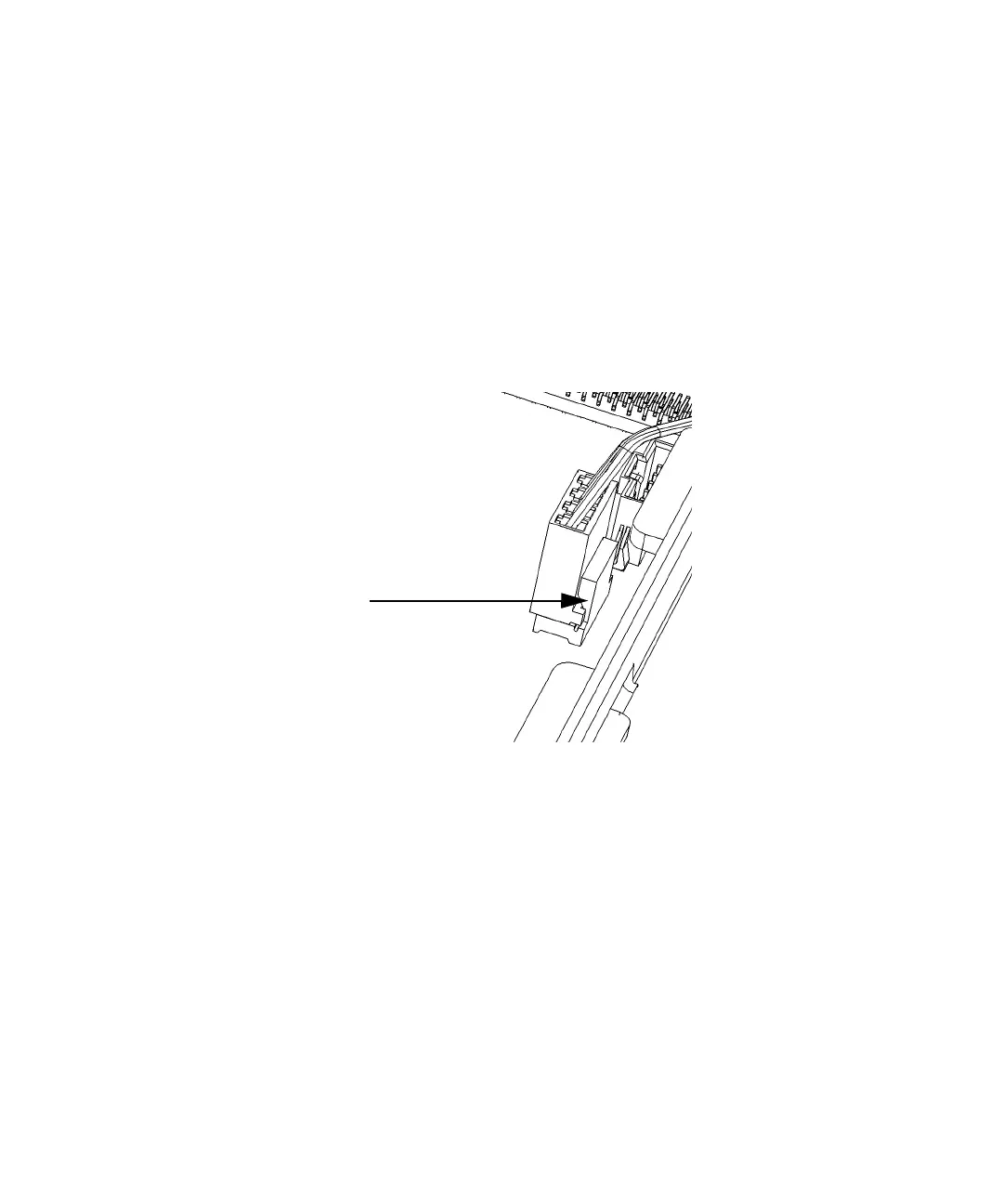
1 Using a medium slot-head screwdriver, gently push back the 4-pin connector
lock tab on the motherboard end of the jumper cable that connects between
the Motherboard (J1000) and the PowerSupply board (J2). Refer to Figure 4-1
andFigure 4-2.
Figure 4-1 Connector Locking Tab
2 Gently move the cable 4-pin connector side-to-side while pulling upward on
the cable connector until the jumper cable is free from the motherboard.
3 Repeat steps 1 and 2 for the other end of the jumper cable where it connects
to the AC power supply assembly (6-pin connector) on the side wall of the
instrument. See Figure 4-2. Set the jumper cable aside in a safe location in
case it is needed in the future.