4 Retrofitting Options
236 Keysight 53210A/53220A/53230A Assembly Level Service Guide
3 Press the two tabs securing the edge connector of the processor board to
release the board.
4 Remove the processor board carefully from its connector and set it aside in a
safe location on the ESD mat.
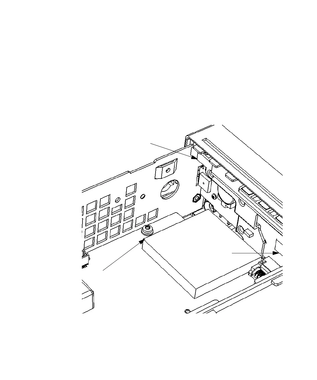
5 Turn the counter chassis upright and position the counter as shown in
Figure 4-18.
6 Remove the T20 TORX screw on the front left-hand side of the motherboard as
shown in Figure 4-18.
Figure 4-18 T20 TORX screw on motherboard
X
T20 TORX Screw
Motherboard
Y