Retrofitting Options 4
Keysight 53210A/53220A/53230A Assembly Level Service Guide 235
Front panel installation procedure (Option 202 only)
1 Remove the front panel assembly as follows:
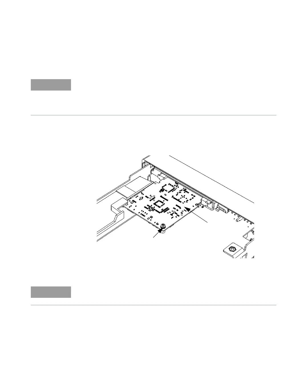
2 Turn the chassis upside down. On the bottom of the motherboard, remove the
T10 TORX screw that secures the smaller processor board to the motherboard
(see Figure 4-17).
Figure 4-17 Processor printed circuit board.
Read each instruction step in its entirety, while examining the hardware and
referring to the appropriate figure(s), before proceeding with the step. This will
acquaint you completely, in advance, with the action to be performed. The
actions in some steps must be accomplished simultaneously to succeed. Read
all nearby NOTES carefully.
P500
PROCESSOR
MOTHERBOARD
T10
TORX
SCREW
BOARD
For re-installation, note how the left rear corner fits into its slot (above the small
plastic standoff inside the slot) to hold the board horizontal.