4 Retrofitting Options
234 Keysight 53210A/53220A/53230A Assembly Level Service Guide
6 Assemble the parts in the Option 106/115 package as follows:
– If Option 115 is being installed, insert and tighten the two supplied
standoffs (using a 1/4" spintite) in the two middle holes closest to the rear
flange of the Channel 2 assembly (Front Panel Option 202 only).
– Position the PC board over the aluminum bracket so that the SMA edge
connector is pointed toward the front flange (without the hole) and sits on
top of the standoffs.
– Install 4 (Option 106) or 6 (Option 115) T10 TORX screws to secure the PC
board to the aluminum deck.
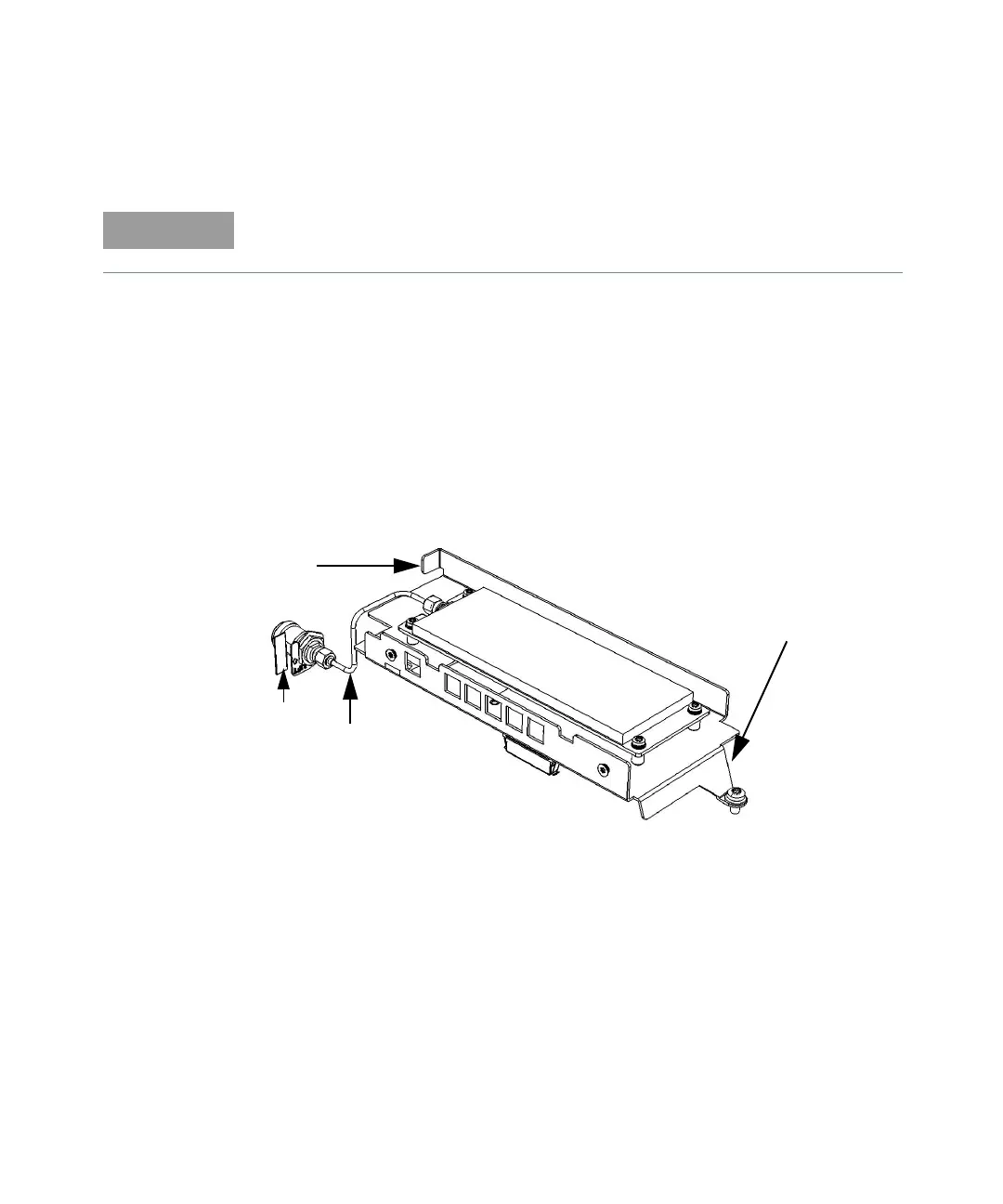
Figure 4-16 53220A/53230A Option 106/202.
Refer as necessary to Figure 4-16.
Front
Rear
Flange
Semi-rigi
d
Cable
Label