Replacing Assemblies 3
Keysight 53210A/53220A/53230A Assembly Level Service Guide 193
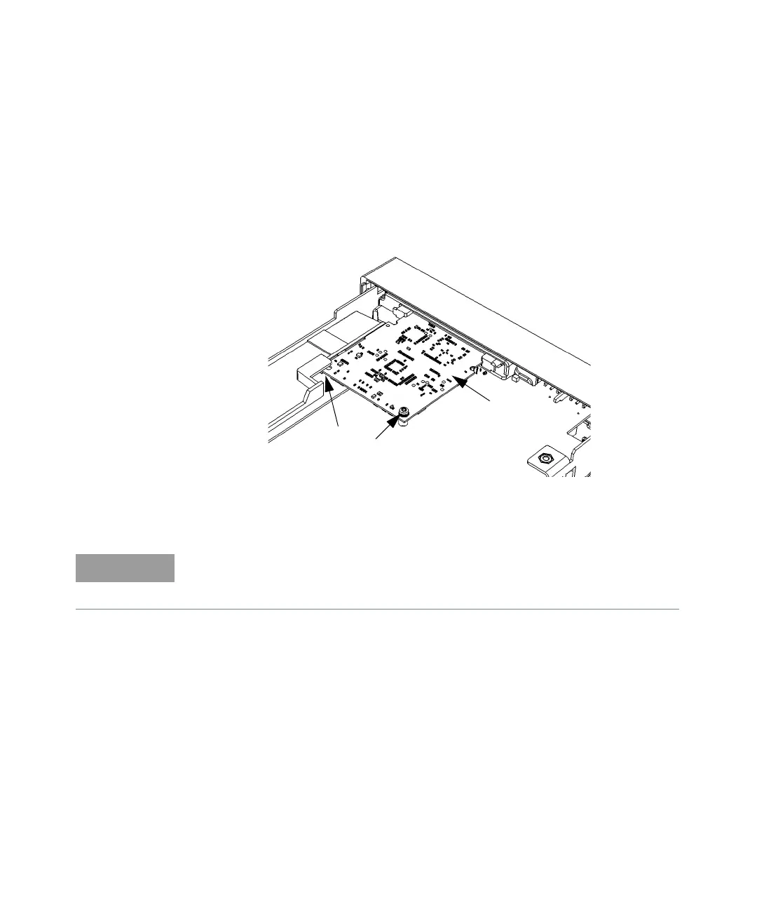
To Remove the Processor Board
1 Remove the cover and rear bezel as described previously.
2 Turn the chassis upside down. On the bottom of the motherboard, remove the
T10 TORX screw that secures the smaller processor printed circuit board to the
motherboard (see Figure 3-6).
Figure 3-6 Processor PC board
3 Press the two tabs securing the edge connector of the processor board to
release the board.
4 Remove the processor board carefully from its connector and set it aside in a
safe location on the ESD mat.
5 To re-install the processor board, reverse the above procedure.
Slot
T10 Motherboard
Processor
For re-assembly, note how the left rear corner of the processor board fits into its
slot (above the small plastic standoff inside the slot) to hold the board
horizontal.