55
LeeBoy 6150 Conveyor Paver 5-19
Maintenance
NOTE: Control boxes are manufactured to t all
screed and paver combinations. If not all
plugs are connected to wires, it may be
normal. Be sure to keep unused plugs
covered with mating protective caps.
• Each element output consists of two wires--one
connects to the L-1 circuit and the other to the L-2
circuit.
• Each breaker has two terminals--one is connected
to the main input and the other terminal to an element
output wire.
• The L-1 circuit is the left bank of element breakers.
• The L-2 circuit is the right bank of element breakers.
Heating element relays “make” or “break” the circuit
to each element to start or stop the heating cycles.
When the HEAT ON button is depressed, 12 VDC is
momentarily applied to the main timer relay to start the
timing cycle.
Element Resistance Testing
The breakers are wired into each leg of each element.
If an element has a fault, either in the wiring, or in the
element itself, the breaker will trip and power will no
longer be applied to that leg of the element.
When a breaker in the control box has “tripped,” there
may be a problem in the wiring or an element in the
circuit.
The breakers can be manually reset by depressing the
trip button back into place when they are extended. If
the breaker still does not reset, you need to test or
possibly replace an element.
If the element is functioning correctly, you should read a
resistance between the connector pins when testing. A
faulty element will show high resistance, indicating a bad
element.
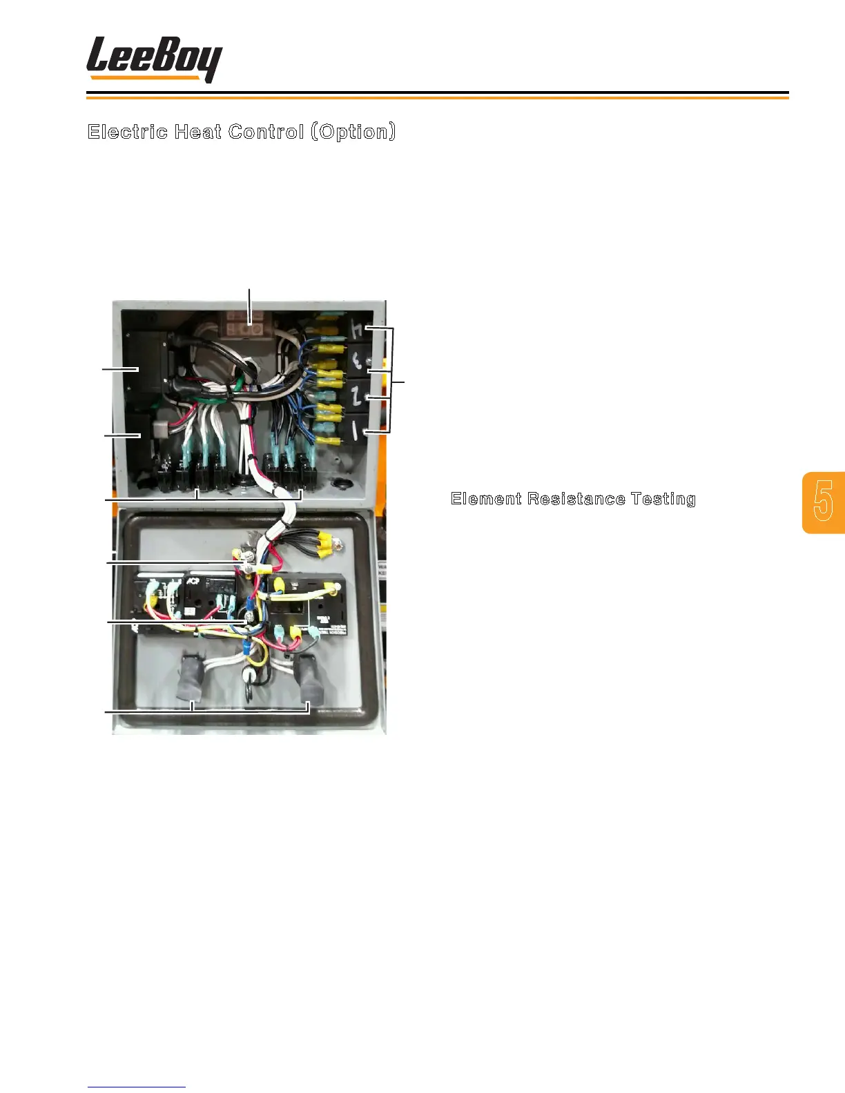
Electric Heat Control (Option)
If equipped with the optional electric screed heat, the
electric heat control box contains element breakers and
main outputs for the system. Powered at 240 VAC, each
element has two circuit breakers. (Figure 5-19)
Refer to the electrical schematic in Section 6 for the
wiring diagram.
1
2
3
4
5
8
6
Figure 5-19. Electric Heat Elements
1 - Generator Circuit Breaker
2 - Generator Timer Controller
3 - Element Circuit Breakers
4 - Power On Toggle
5 - Heat On Button
6 - Toggle for Left/Right Endgates
7 - Wire Junction Block
8 - Heating Element Relays
 Loading...