4-4 LeeBoy 6150 Conveyor Paver
Operation
Start-Up Procedure
DO NOT leave the operator station
unattended while the paver is in gear or in motion.
Operator must return joystick(s) to the neutral
position and turn the RUN/STOP switch to the STOP
position before leaving the operator platform.
Verify there are no people, obstacles
or other equipment in the machine’s path before
starting the engine.
1. Ensure auger and conveyors are clear of material or
any obstructions before starting engine.
2. Position both steering panel joysticks in the
NEUTRAL (center) position and the Run/Stop
switches in the STOP position. Activate the desired
operator station. (Page 4-19)
3. Insert key into the ignition on the main control panel
and turn clockwise to the START position. The “Wait
to Start” light on the control panel will illuminate.
4. Wait for the “Wait to Start” light to turn off, then turn
key to the RUN position to start.
NOTE: The “Wait to Start” light will stay on but the
engine will not start if either joystick is not in
neutral.
DO NOT hold the starter longer than
10 - 15 seconds. If the engine does not start, allow
the starter to cool two or three minutes.
Using starting additives, such as
ether, is not recommended as severe engine damage
can occur.
NOTE: Allow engine to warm up a few minutes before
moving paver for more efcient operation. In
cold weather, allow hydraulic oil to warm to
60° (16°C) before moving.
Stopping the Engine
1. Move joystick to the NEUTRAL position and the Run/
Stop switch to the STOP position.
2. Reduce engine to idle speed (1300 RPMs).
3. Turn ignition key on the main control panel
counterclockwise to the OFF position and remove
key.
NOTE: If the engine does not shut down when key is
turned OFF, press the E-Stop button on the
control panel to terminate power.
Hopper and Screed Lock Pins
This machine is provided with both hopper and screed
lock pins on each side as added safety and stability dur-
ing operation and transport.
Ensure lock pins are in the unlocked
position before extending or retracting hopper wings
and screed.
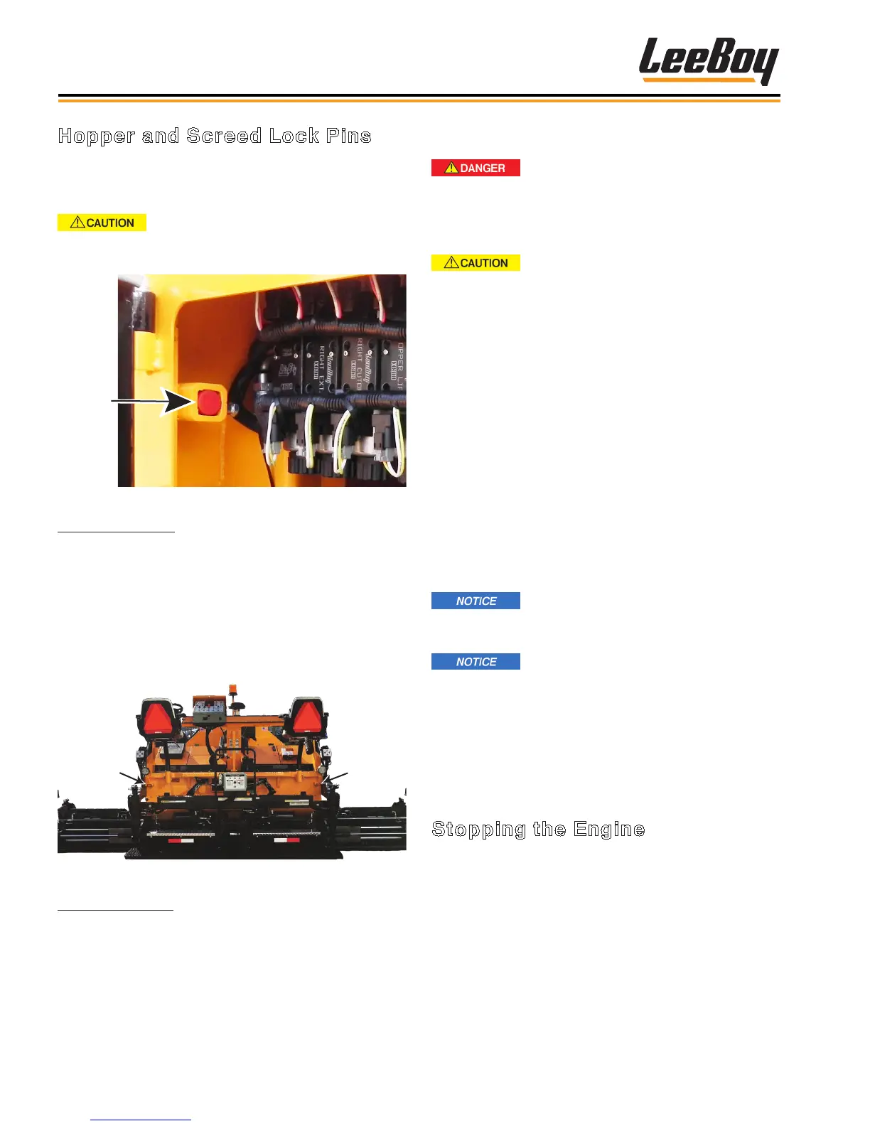
Hopper
Lock Pin
Figure 4-1. Hopper Lock Pin
Hopper Lock Pins:
The hopper lock pins are located just inside the right
and left engine access panels (front side of compart-
ment). Figure 4-1 shows the hopper lock pin in the
unlocked position.
To unlock: Lift bolt handle, slide lock pin back and drop
lift bolt into place. Reverse procedure to lock the hop-
per.
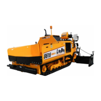
Screed
Lock
Screed
Lock
Figure 4-2. Screed Lock Pin Locations
Screed Lock Pins: Figure 4-2 shows the screed lock
locations.
To lock: Unscrew wing nut, slide lock pin and screw
wing nut into place. Reverse procedure to unlock the
screed.