5-8 LeeBoy 6150 Conveyor Paver
Maintenance
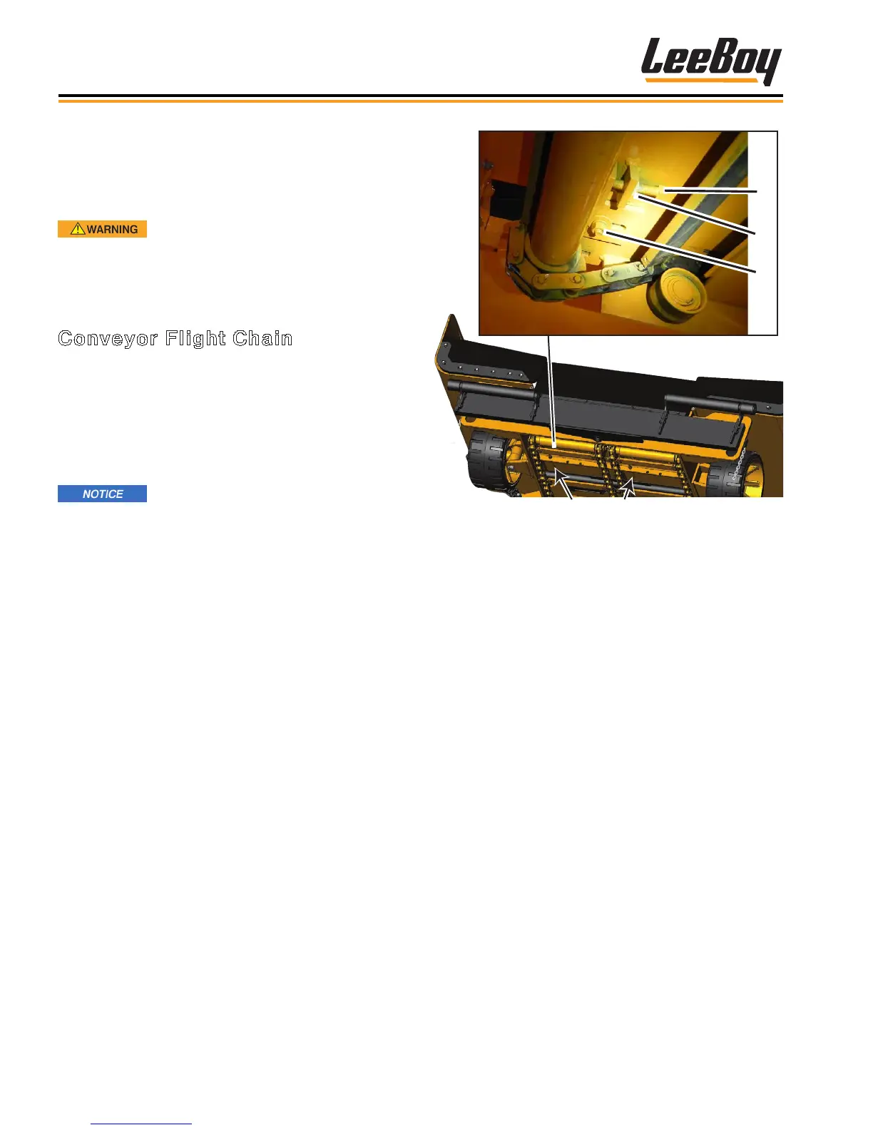
Figure 5-3. Conveyor Flight Chain Adjustment
1 - Adjustment Bolt
2 - Locking Nut
3 - Hold-Down Nut
4. Turn each adjustment bolt alternately the same
amount. For example, turn one bolt one half turn,
then the other bolt one half turn, etc.
5. Continue alternating tightening until the ight chains
are tight. (The pressure on the chain will be notice-
able as the bolts are tightened.)
NOTE: Drag chains should be 1/2-inch away from
rear frame channel.
6. After the conveyor chain tension is set, retighten
locknuts and bolts holding the ight chain assembly.
7. Repeat steps 1 through 4 for the opposite side.
8. Grease front and rear conveyor tubes at grease
blocks on each side of conveyor.
Maintenance Adjustments
Certain components of the paver need adjustments
for optimum performance, operation and general
maintenance.
Entanglement hazard! DO NOT run
the engine while checking and servicing conveyor
components. NEVER perform any adjustments while
the engine is running.
Conveyor Flight Chain
Maintaining the two conveyors in proper adjustment
will ensure maximum service life from the conveyors,
sprockets and shafts. The conveyor ight chains must
be adjusted every 100 hours for optimum performance.
(Figure 5-3) If irregular movement of the conveyor
occurs, an adjustment is needed regardless of the time
interval. (See Page 5-33 for slack tension adjustment.)
Keep conveyor ight chain properly
oiled with cleaning solvent or release agent during
cold weather to keep conveyors functioning
smoothly.
NOTE: If the adjustment bolt has reached its
maximum adjustment level, remove the half
link in the conveyor chain. This repair should
bring the adjustment bolts back to full travel.
There are four (4) adjustment bolts, two (2) for each
conveyor. Use the following procedure to make this
adjustment on both sides of the conveyor:
1. Move front of paver onto a ramp and block with
wheel chocks to prevent the paver from moving.
2. Loosen the hold-down nuts (one on each side of
each adjustment bolt). (Figure 5-3)
3. Loosen each locking nut beside the adjustment bolt.