Electrical installation
Motor connection
5
146
EDK82EV903 DE/EN/FR 5.1
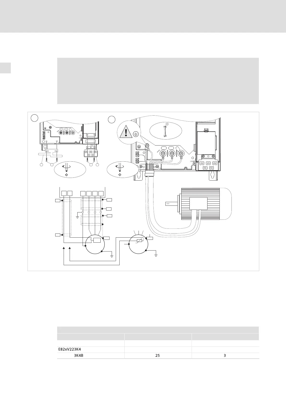
5.3.4 Motor connection
Danger!
ƒ All control terminals only have basic insulation (single isolating distance)
after connecting a PTC thermistor or a thermal contact.
ƒ Protection against accidental contact in case of a defective isolating
distance is only guaranteed through external measures, e. g. double
insulation.
U
VW
PE
T1
T2
PE
U, V, W,
PE
5 Nm
44 lb-in
M 6
T1
T2
2,5 Nm
22.1 lb-in
g
k
2,5 Nm
22.1 lb-in
1
g
f
k
e
PE
PE
M
3~
M
3~
PTC
PE
PES
PE
U
V
W
T1
T2
J>
PES
PES
PES
PES
PES
PES
8200vec285
Use low−capacitance motor cables! (core/core £ 140 pF/m, core/shield £ 230 pF/m)
The shorter the motor cable, the better the drive behaviour!
PES HF shield termination by PE connection through shield clamp.
T1, T2 Terminals of motor temperature monitoring with PTC thermistor or thermal
contact (NC contact).
Lay a separate cable (shielded) to X2/T1 and X2/T2 for motor temperature
monitoring.
Activate motor temperature monitoring with C0119 (e.g. C0119 = 1)!
Lay the control and mains cables separately from the motor cable!
Cable cross−sections U, V, W, PE
8200 vector mm
2
AWG
E82xV153K4B 10 8
E82xV223K4B
16 6
E82xV303K4B
25 3
 Loading...


