Extensions for automation
Modules
Wiring of controller inhibit (CINH) when two function modules are operated
6
166
EDK82EV903 DE/EN/FR 5.1
6.1.3 Wiring of controller inhibit (CINH) when two function modules are operated
Note!
ƒ Both terminals X3/28 of the interface FIF I and FIF II are evaluated internally
via an AND−operation.
ƒ The following illustrations show possible methods of wiring. Considering
the AND−operation of both terminals X3/28, wiring can be adapted to your
application.
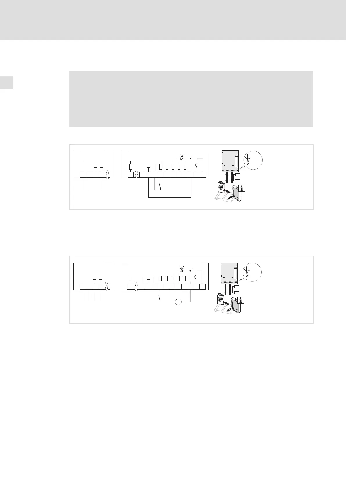
Internal DC voltage supply
FIF I
39
7
+20V
2820
X3
GND3 GND1
62 9
7
20 28
E1 E2
E3
E4
39
A1
59
E82ZAFSC010E82ZAFx
FIF II
+20V
+5V
X3
GND1
GND2
0.5...0.6 Nm
4.4...5.3 lb-in
X3
PES
PES
0
8200vec262
For function modules with terminals X3/7 and X3/39: Install a wire jumper between X3/7
and X3/39
PES HF shield termination by large−surface connection to PE
Wiring of the other terminals: Mounting instructions of the function modules
External voltage supply
FIF I
39
7
+20V
2820
X3
GND2 GND1
62 9
7
20 28
E1 E2
+
–
E3
E4
39
A1
59
E82ZAFSC010E82ZAFx
FIF II
+20V
24 V ext.
(
+30 V +0 %, max. 120 mA)
+12V-0%...
…
+5V
X3
GND1
GND2
0.5...0.6 Nm
4.4...5.3 lb-in
X3
PES
PES
0
8200vec263
For function modules with terminals X3/7 and X3/39: Install a wire jumper between X3/7
and X3/39
PES HF shield termination by large−surface connection to PE
Wiring of the other terminals: Mounting instructions of the function modules

 Loading...


