Electrical installation
Connection of relay output K
SR
5
158
EDK82EV903 DE/EN/FR 5.1
Technical data
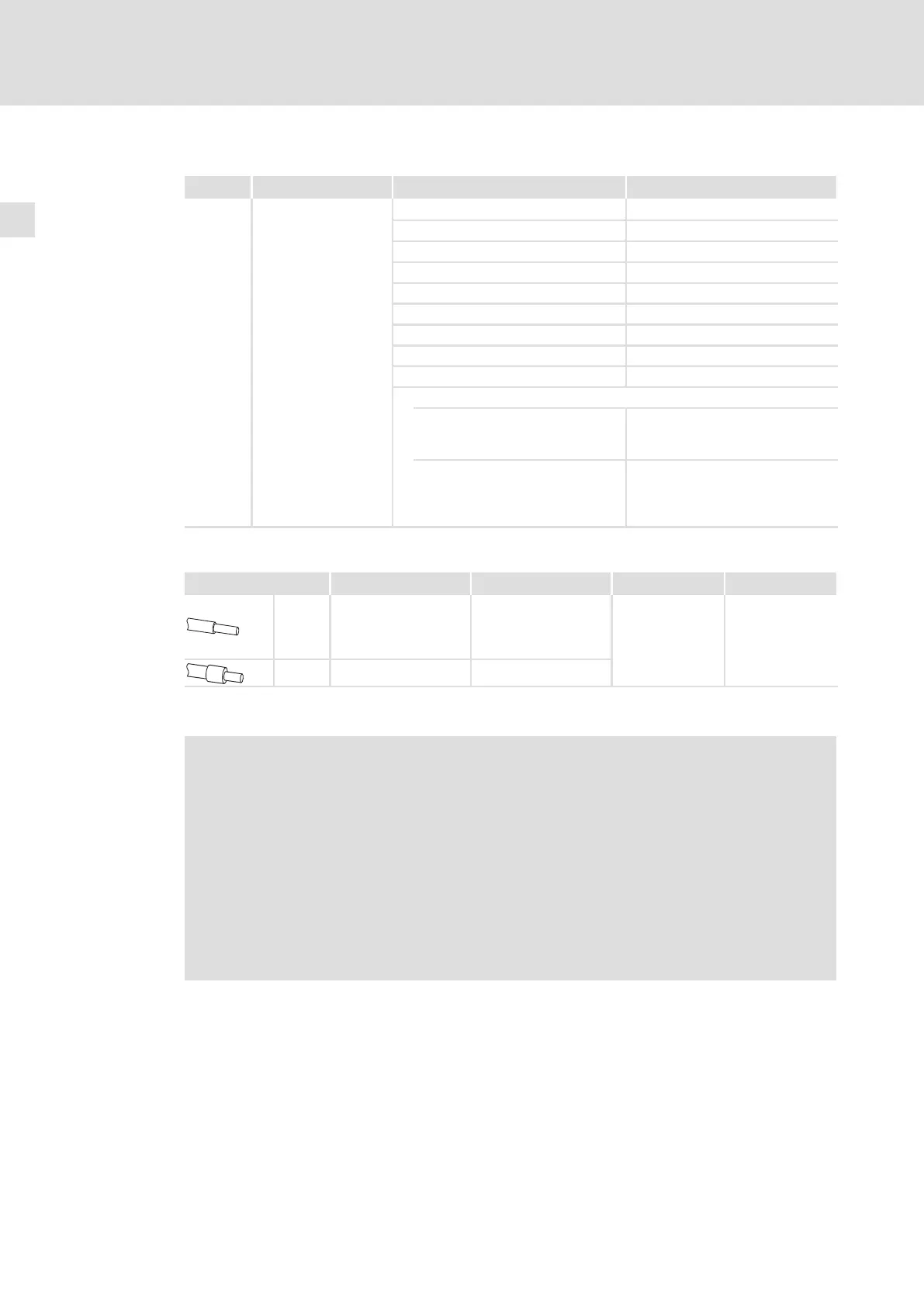
Terminal Description Range Values
X3.1/K32
X3.1/K31
X3.1/33
X3.1/34
Safety relay K
SR
1st disconnecting path
Coil voltage at +20 °C DC 24 V (20 ... 30 V)
Coil resistance at +20 °C 823 W ±10 %
Rated coil power Approx. 700 mW
Max. switching voltage AC 250 V, DC 250 V (0.45 A)
Max. switching capacity, AC 1500 VA
Max. switching current (ohmic load) AC 6 A (250 V), DC 6 A (50 V)
Recommended minimum load > 50 mW
Max. operating frequency 6 switching operations per minute
Mechanical service life 10
7
switching cycles
Electrical service life
at AC 250 V
(ohmic load)
10
5
switching cycles at 6 A
10
6
switching cycles at 1 A
10
7
switching cycles at 0.25 A
at DC 24 V
(ohmic load)
6 × 10
3
switching cycles at 6 A
10
6
switching cycles at 3 A
1.5 × 10
6
switching cycles at 1 A
10
7
switching cycles at 0.1 A
Terminal data
Cable type Wire end ferrule Cable cross−section Tightening torque Stripping length
Directly
coupled
to the
mains
— 2.5 mm
2
(AWG 14)
0.5 ... 0.6 Nm
(4.4 ... 5.3 lb−in)
5 mm
Flexible With plastic sleeve 2.5 mm
2
(AWG 14)
Wiring
Danger!
Faulty operation in case of earth faults possible
The correct functioning of the safety function is not ensured if an earth fault
occurs.
Possible consequences:
ƒ A failure of the safety function can lead to death, severe injuries or damage
to material.
Protective measures:
The electrical reference point for the coil of the safety relay K
SR
must be
connected to the PE conductor system (EN 60204−1, paragraph 9.4.3)!
 Loading...


