Erweiterungen für die Automation
Module
Funktionsmodule montieren und demontieren
6
68
EDK82EV903 DE/EN/FR 5.1
Montage
8200vec621
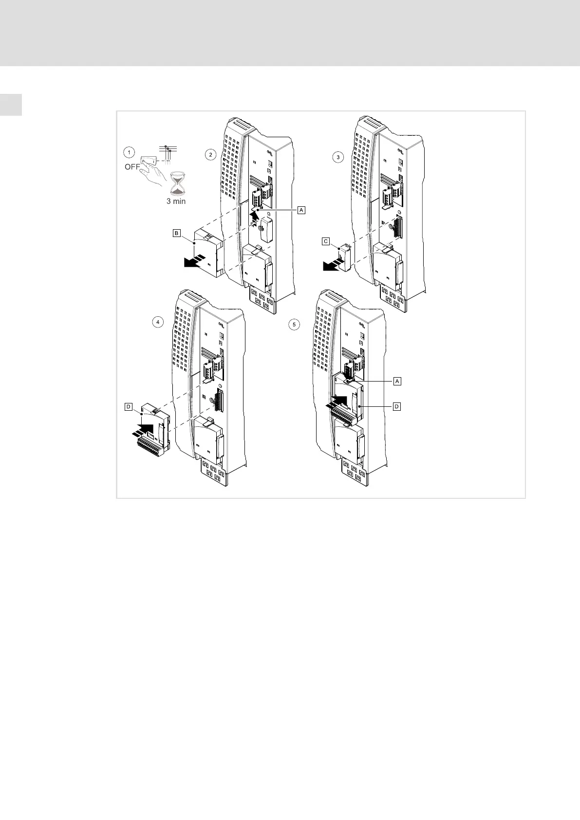
Die folgenden Arbeitsschritte gelten sowohl für die Schnittstelle FIF I (oben) als auch für die
Schnittstelle FIF II (unten).
1. Antriebsregler vom Netz trennen und mindestens 3 Minuten warten!
2. Lasche vorsichtig nach oben drücken und Blindkappe abziehen.
3. FIF−Abdeckkappe abziehen.
4. Funktionsmodul auf die Klemmen der Schnittstelle stecken.
– Achten Sie darauf, dass die Stifte der FIF−Schnittstelle korrekt in den Buchsen am
Funktionsmodul stecken und nicht verbogen werden.
5. Funktionsmodul andrücken bis die Lasche einrastet.
– Ohne FIF−Abdeckkappe ist der Regler gesperrt.
– Wenn kein Funktionsmodul gesteckt ist, darf der Antriebsregler ohne
FIF−Abdeckkappe und Blindkappe nicht in Betrieb genommen werden
(gefährliche elektrische Spannungen an der FIF−Schnittstelle).
 Loading...


