Page 144
Figure 7: DMX Recommended Wire
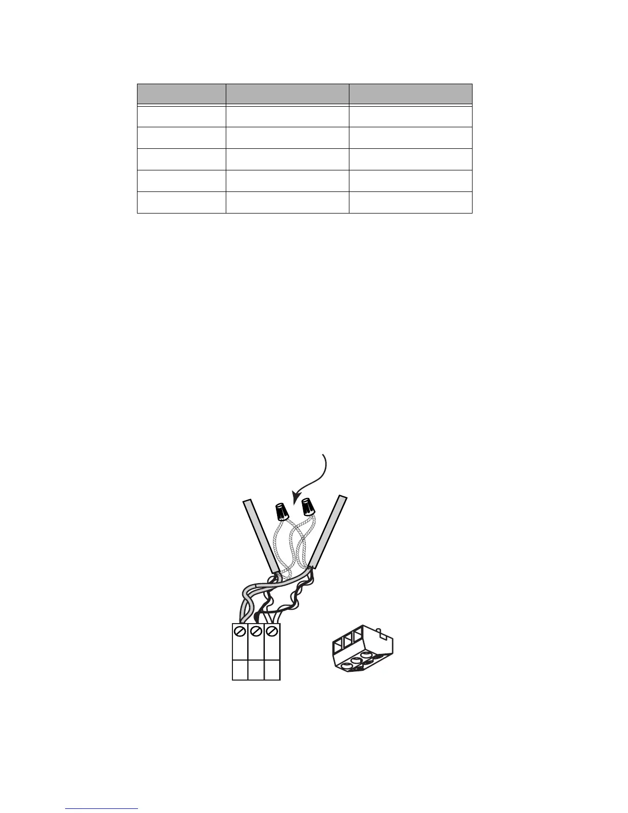
Wiring the DMX Connector
Step 1: Connect leads per the following wiring diagram.
Step 2: Twist strands of each lead tightly (making sure that there are no stray
strands) and push firmly into appropriate plug connector location.
Step 3: Tighten the screws on the plug connector—making sure that no bare
conductor is showing.
Step 4: Tie the Drain/Shield wires together and insulate using a small piece of
heat shrink tubing.
Step 5: Install termination jumpers as required. Termination can be accomplished
on the control board by jumpering the 2 pin header to the left of the
DMX connector.
Figure 6: Z-Max DMX connector wiring
Manufacturer Catalog Number # of Pairs
Belden 9729, 9829, 8102 2
Belden 9841 1
Belden 89729, 88102 2 (Plenum Rated)
Alpha 6222C 1
Alpha 6412 1
COM
DATA -
Data +
1
2
3
DMX Connector (Blue)
DMX IN
DMX OUT
1
2
3
Data 2 +/-