Page 152
Connection Methods
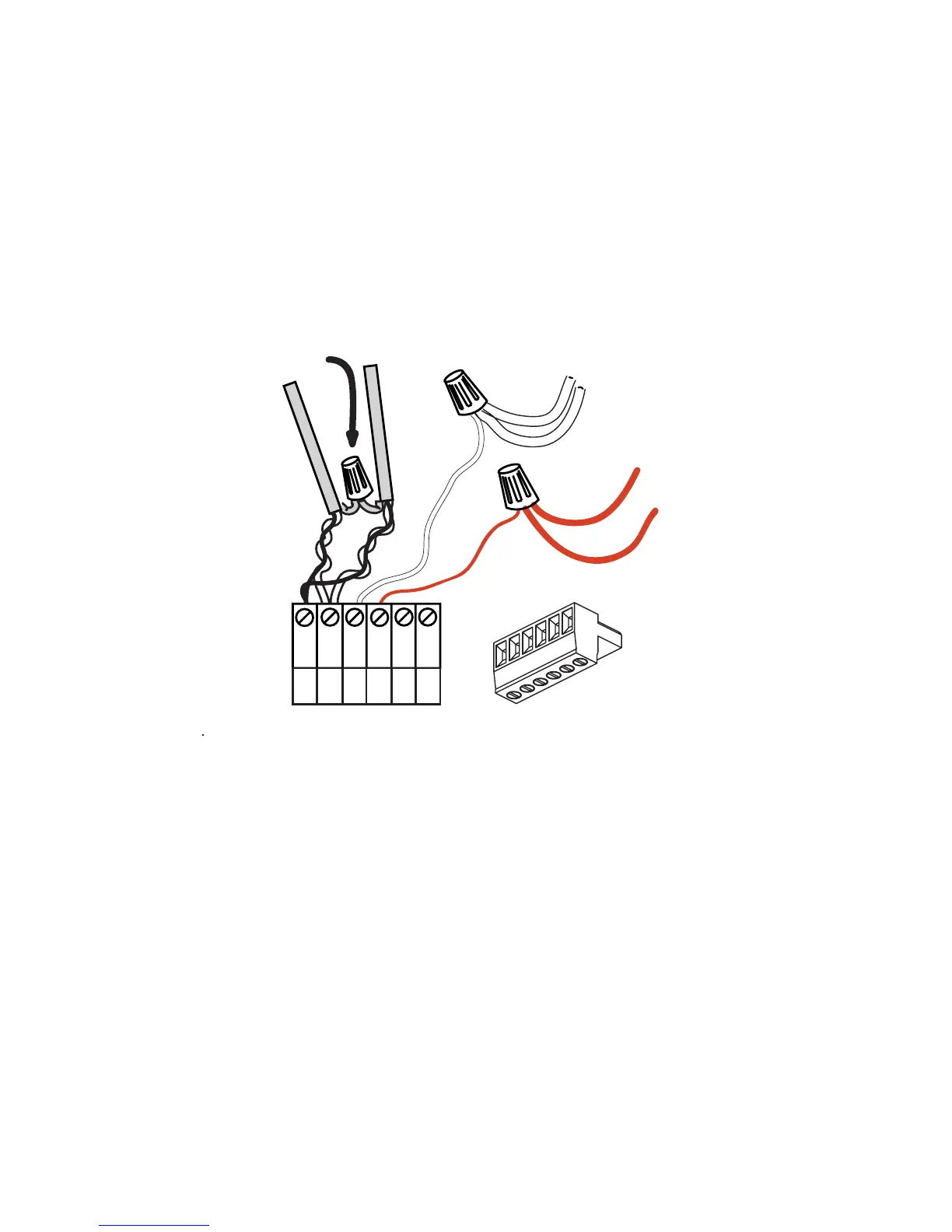
Wiring the Phoenix Connector
Step 1: Connect leads per the following wiring diagram
Step 2: Twist strands of each lead tightly (making sure that there are no stray
strands) and push firmly into appropriate plug connector location.
Step 3: Tighten the screws on the plug connector—making sure that no bare
conductor is showing.
Step 4: Tie the Drain/Shield wires together and insulate using a small piece of
heat shrink tubing.
Step 5: Install termination jumpers as required. Termination jumpers are
required at the two ends of the Luma-Net run. The termination can be
accomplished on the Luma-Net connector with a jumper wire as shown
below. Termination can also be accomplished on the control board by
jumpering the 2 pin header to the left of the Luma-Net connector.
Testing the Wiring
To assure problem-free start-up, it is important to check the system wiring, prior to
hooking up any control stations, for proper connections, shorts and opens.
The following procedure is recommended:
Step 1: Test the following wire pairs for shorts at each station location, using an
ohmmeter or other continuity tester.
1-2 Open
2-3 Open
3-4 Open
REM+
REM -
COM
TERM
LOCK
+V
1
2
3
4
5
6
Up to 1 #12AWG
2#12AWG
2#12AWG
Up to 1 #12AWG
Drain/Shield - Insulated and tied together
(Ground at one point only-
probably an end)
Red
(+V )
Black (Common)
5
6
1
2
3
4
Phoenix/Luma-Net Connecto