Page 162
Regardless of the pinout of your particular product, the common designations for
terminals are as follows:
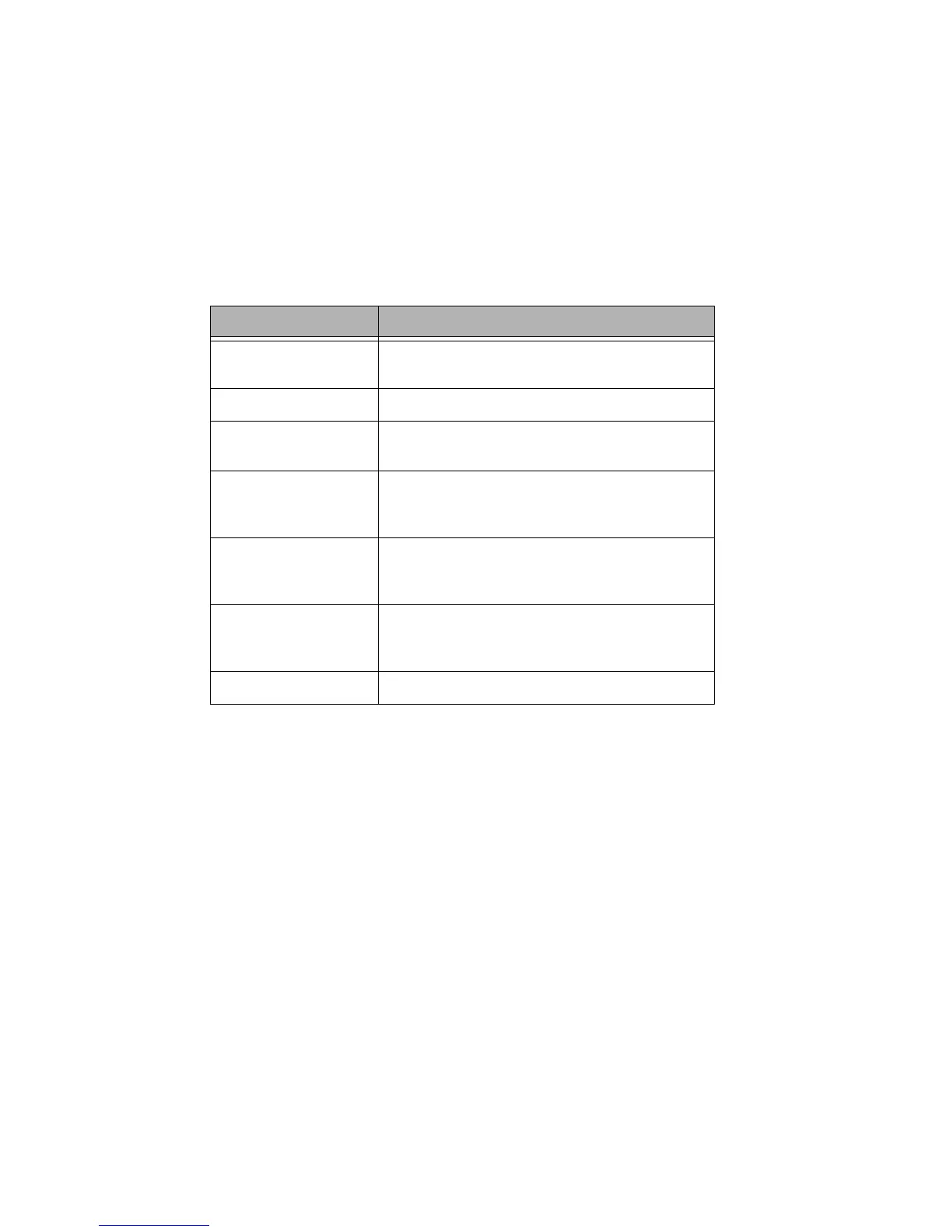
Figure 9: Discreet input terminal labels and their meaning
By default the "IN" or the "ON" terminal is expecting +V to trigger as would be typical
with many styles of low voltage switches. If a connection to common is required, it
requires some jumper and software re-configuration. For more information on this
topic, please reference the discussion on input triggers found on page 156.
Connecting Low Voltage Switch
Step 10: Strip each wire from your device and tightly twist the wires together
Step 11: Insert the wires from the device into the connector on the relay cabinet
in the appropriate location
Step 12: Tighten the terminal screw, and repeat for all wires from the device
Step 13: Plug the terminal block back into the cabinet with the screws facing
towards you and the wires exiting towards the side or top of the cabinet.
Alternatively, the connector can be inserted with the screws parallel to
the circuit board and the wires exiting towards you
Step 14: Verify that the wires land on the correct terminals
Pin Label Function
+24V Supplies +24Vdc power to devices, usually
unregulated
COM Connection to DC Common of the cabinet
IN Switch Input or signal from device. Usually
expecting +V to trigger.
OUT Used for connection to device LED indicating on/off
state of that input. Connects to common when on,
floats when off. (Max 0.04A)
LED Used for connection to device LED indicating on/off
state of that input. Connects to common when on,
"floats" when off. (Max 0.04A)
ON Usually can be configured identically to the IN
terminal but can be configured as Momentary ON
input only
OFF Momentary OFF input only