Switch/Discrete Inputs
Z-Max Advanced Programming & Systems Design Guide rac00-sdg
Revision A:11/2005 Page 69
Switch/Discrete Inputs
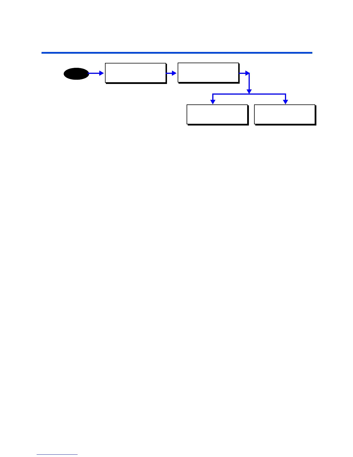
The inputs section of the configuration menus allows you to configure all of the local
and remote switch inputs to your relay cabinet. Configuring any switch input is a two-
step process:
Step 1: Define the type of switch input
Step 2: Assign actions and behaviors to that input
The define types menu is where you define the type of device or function of the input,
and the assign actions menu is where you define what happens when an input signal
(or lack thereof) is received at the particular input.
The system accepts the following switch Input types:
• Low Voltage Switches
• Momentary
• Preset ON
• Preset OFF
• Maintained
• Momentary Timed
• Momentary On/Off
• Digital Switches
• Occupancy Sensors
• Photocells
• Contact Closure Inputs
• Remote Inputs from a master/remote network connected panel
Switch Numbering
There are a maximum of 240 definable switch inputs in the programming structure.
These inputs are allocated first to any local inputs, second to any remote inputs from
master/remote connected panels, and lastly to network switches.
The first available input for a digital switch can be calculated as 1+[number of local
relays]+[number of remote relays]. For example, if in the global defaults you had
defined 24 local relays and 48 remote relays, then your relay number would be as
follows:
• 1-24 local inputs
MAIN MENU SELECT
CONFIGURATION
MENU
CONFIGURATION
INPUTS
DISCRETE INPUTS
DEFINE TYPES
DISCRETE INPUTS
ASSIGN ACTIONS