Page 164
Step 6: Re-install the control module following in reverse the steps followed for
removal.
Modem Module Installation on Z-Max relay Panels
Prior to touching any part of any electronics, make sure that you first
touch any grounded metal surfaces so that you can discharge any
build up of static electricity.
Step 1: Disconnect Power from the cabinet
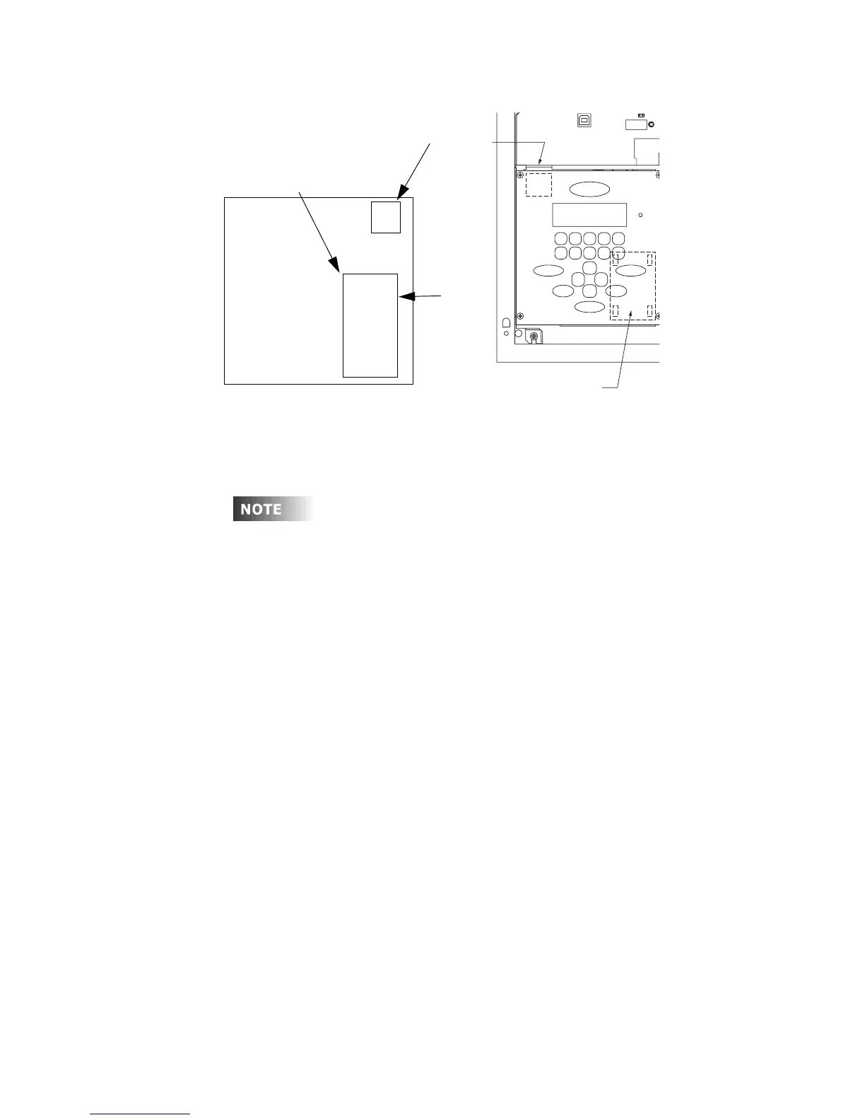
Step 1: Locate the modem socket on your control module
Step 2: Remove the modem module from it’s packaging, and install into the
modem socket by aligning the gold dot with the location shown in the
illustrations, aligning the pins into the socket, and then gently but firmly
pressing the modem into place. Reference the drawing below which
shows the correct orientating of the modem.
1A 2A G
SLOW BLO W FUSE
USB
Connector
RJ Connector
for Modem
Socket for
Optional Modem
Looking at CM from Back
Modem
Modem Pin 1
(Gold Dot)