Page 156
Control Wiring Termination
This section gives instructions for terminating all types of low voltage inputs.
• Leviton recommends minimum 18AWG stranded wire for all low voltage wiring
• Terminate all control wiring directly to the terminal blocks on the printed circuit
board. Use a small 1/8-in. flat screwdriver on these terminals
• Terminal blocks are 2-part terminals and can be removed for ease of termination.
When reinstalling them make sure they are plugged in the correct direction for the
way they were wired
• On the 4 relay remote panel, models re4sd-*, inputs #5 & #6, labeled photocell
and occupancy sensors can not be used
• All control wiring shall be considered Class 2
• Use control wire type and size as specified below:
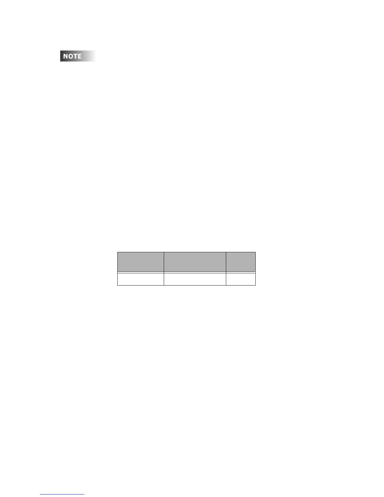
Figure 6: Control Wire Type and Size
Input Trigger - What determines an "ON"
Each of the low voltage inputs can be triggered by either the supply of voltage or a
connection to common. When voltage is supplied to an input indicating a change of
state, we call this "pulling up the input" or "active high." When a connection to
common triggers the input, causes a change of state, we call this "pulling down the
input" or "active low."
By default, all inputs are active high (that is receiving voltage to trigger). Active High
inputs must not exceed a nominal +24VDC and must be above +9vdc. Active Low
inputs must connect to the same common at the same potential as the cabinet.
To change from an active high input to an active low input, three things must occur.
First, the polarity jumper must change position. Second, if you intent to use the
output terminals, the polarity IC’s must be changed. Finally, the switch input must be
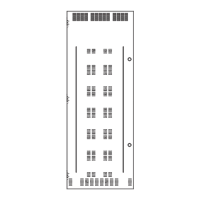
configured as an "active low" input. The location of the polarity IC’s and the location
of the polarity jumper is shown in figures 5-7 which follow. Information on input
programing is covered in the following sections.
Connector
Type
Wire Size and type To rq ue
Switch Inputs 14-24 AWG, Stranded 2 in-lb.
Each product (and in some cases each model of a product) has
a slightly different layout at the terminals blocks. The specific
functions of each terminal is labeled on the circuit board
adjacent to the terminal blocks. When wiring the inputs, verify
that you are connecting the correct wire to the correct terminal
based on function even if it deviates from that shown in this
documentation. Contact our technical services department with
any undocumented questions.