8 - 12 CHAPTER 8 : OPERATION
TRYTON 112 CNC
4
5
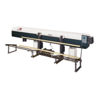
6
7
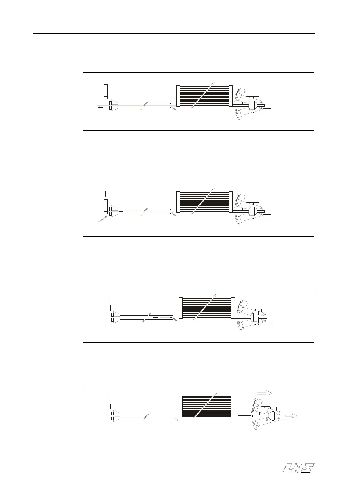
4. The pusher advances and positions the bar in the lathe clamping device.
The lathe clamping device closes. The production cycle begins.
5. If there is not enough material left to make another piece when the barfeeder collet
draws close to the lathe clamping device, the end-of-rod signal is given and the
barfeeder enters in the loading sequence.
6. The hydraulic motor reverses the direction of rotation and draws the oil into the
guidance tube. Drawn by the retraction cable, the pusher moves back and recovers
the remainder of the material.
7. When the pusher is locked into the connector, the hydraulic motor stops turning
and the connector retracts, taking the mobile vice with it.