6. Function Description
6-73
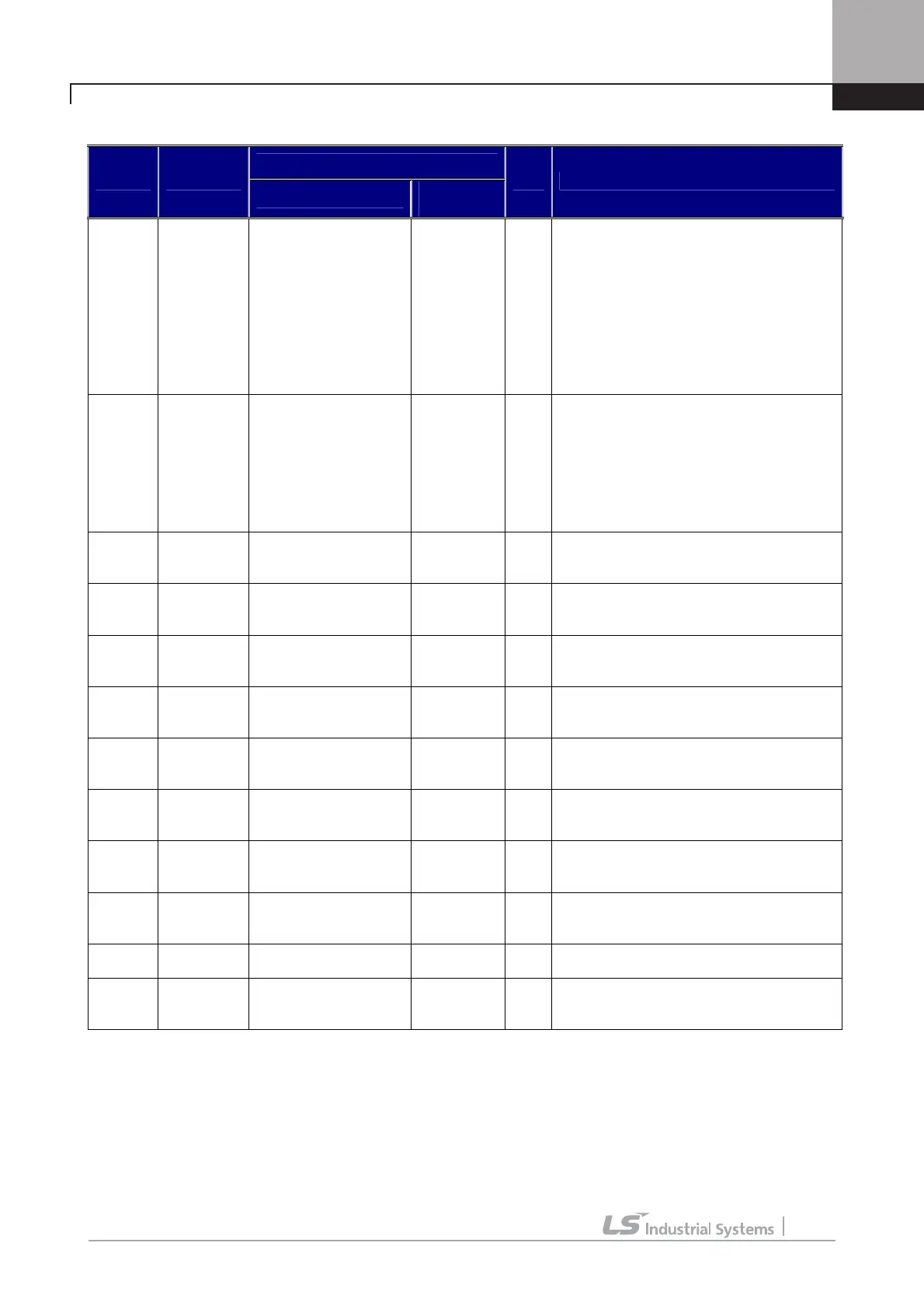
Code setting about analog command definition is as follow.
Definition
Code Display
Name
Setting
range
Unit Function Description
AIO_01 Ai1 Define
Definition
of Multi function
analog input Ai1
Speed Ref
Proc PID Ref
Proc PID
F/B
Draw Ref
Torque Ref
Flux Ref
Torque Bias
Torque Limit
It defines the type of Multi function analog
input Ai1.
AIO_02 Ai1 Source
Definition
of input source of
Multi function analog
input Ai1
-10 Æ 10V
10 Æ -10V
0 Æ 10V
10 Æ 0V
0 Æ 20mA
20 Æ 0mA
It defines input source of Multi function
analog input Ai1.
AIO_03 Ai1 In X1
Min. input of
Multi function analog
input Ai1
0.00 ~ Ai1
In X2
%
It sets Min. value of analog input.
Without reference to AIO_02 set value, it is
based on 0[V](voltage) or 0[mA](current)
AIO_04 Ai1 Out Y1
Min. input Bias of
Multi function analog
input Ai1
-10.00
~ Ai1 Out
Y2
%
It defines the set value of AIO_01
responding to analog input value of AIO_03.
AIO_05 Ai1 In X2
Max. input of
Multi function analog
input Ai1
0.00 ~
100.00
%
It set Max. input value of analog input
value.
AIO_06 Ai1 Out Y2
Max. input gain of
Multi function analog
input Ai1
0.00 ~
250.00
%
It defines the set value of AIO_01
responding to analog input value of AIO_05.
AIO_07 Ai1 In -X1
-Min. input of
Multi function analog
input Ai1
Ai1 In X2 ~
0.00
%
It sets -Min. value of analog input.
Without reference to AIO_02 set value, it is
based on 0[V](voltage) or 0[mA](current)
AIO_08 Ai1 Out -Y1
-Min. input Bias of
Multi function analog
input Ai1
Ai1 Out Y2
~ 10.00
%
It defines the set value of AIO_01
responding to analog input value of AIO_07.
AIO_09 Ai1 In -X2
-Max. input of
Multi function analog
input Ai1
-100.00 ~
0.00
%
It set -Max. input value of analog input
value.
AIO_10 Ai1 Out -Y2
-Max. input gain of
Multi function analog
input Ai1
-250.00 ~
0.00
%
It defines the set value of AIO_01
responding to analog input value of AIO_09.
AIO_11 Ai1 LPF
Input LFP time
constant of Ai1
0 ~ 2000 ms It sets LPF time constant about analog input
AIO_12
Ai1
Wbroken
Option for criterion of
command loss of Multi
function analog input
None
Half of x1
Below x1
It chooses criterion of command loss of
analog input Ai1
AIO_13 ~ AIO_36(Ai2 ~ Ai3) are the same with the analog input 1(Ai1) above. (In the case of EXTN_I/O, same up to
AIO_37 ~ AIO_60(Ai4 ~ Ai5). But in the case of Ai3 and Ai5, there is no current input.
AIO_03 Ai1 In X1 displays the analog input voltage or analog min. input current that inverter recognize as % unit.
It means the percentage(%) of max.input voltage 10[V] or max. input current 20[mA]. For example, if you set AIO_03
Ai1 In X1 as 20[%], the voltage becomes 2[V], the current becomes 4[mA]. And if AIO_04 Ai1 Out Y1 is set as 0[%],

 Loading...


