6. Function Description
6-74
the analog input value that is under voltage 2[V], or current 4[mA] that is fed into analog input terminal will not be
recognized.
AIO_04 Ai1 Out Y1 sets the min. level of analog input voltage or current that inverter actually recognizes. For example,
if you set AIO_03 Ai1 In X1 as 0[%] and set AIO_04 Ai1 Out Y1 as 20[%] and then, you feed into analog input
terminal voltage 2[V] or current 4[mA], when the actual analog input voltage or current that inverter recognizes is 0,
inverter recognizes as 20[%].
AIO_15 Ai1 In X2 displays the analog input voltage or analog max. input current that inverter recognize as % unit.
For example, if you set AIO_05 Ai1 In X2 as 50[%], when the actual voltage or current that is fed into analog input
terminal is more than 5[V] or 10[mA], inverter recognizes it as max. analog input value.
AIO_06 Ai1 Out Y2 sets the max. level of analog input voltage or current that inverter actually recognizes.
For example, if you set AIO_05 Ai1 In X2 as 100[%] and AIO_06 Ai1 Out Y2 as 50[%], although the voltage 10[V] or
the current 20[mA] is actually fed into analog input terminal, inverter recognizes the final analog input value as 50[%].
If you set as above and the rated speed is 1800[rpm], you cannot set more than 900[rpm] although you feed 10[V] into
analog input terminal
.
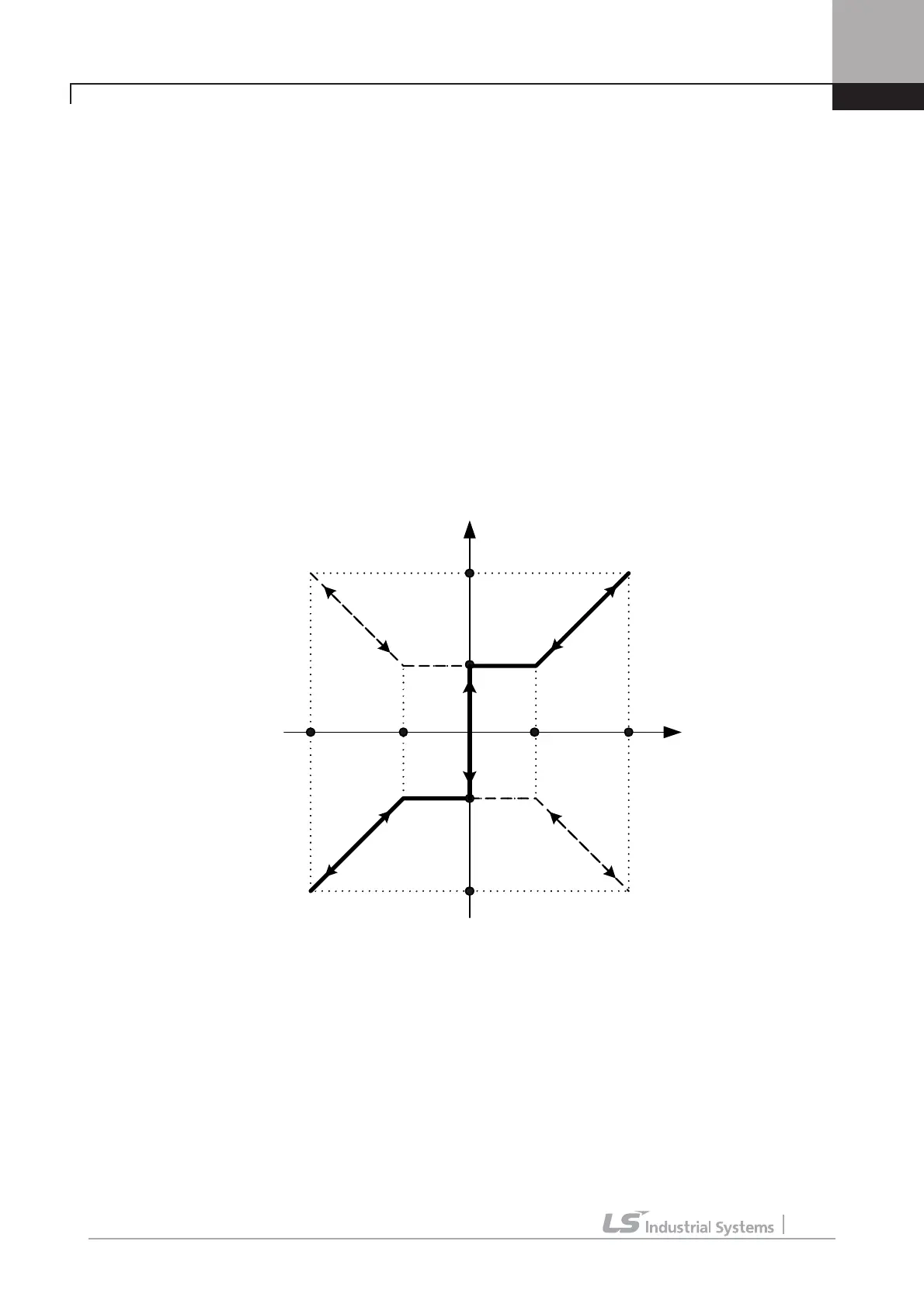
Analog input Mapping diagram
AIO_03 Ai1 In X1 and AIO_05 Ai1 In X2 are for setting the allowed range of voltage of current that is fed into analog
input terminal, so generally you can set AIO_03 Ai1 In X1 as 0[%], and AIO_05 Ai1 In X2 as 100[%]. But, the analog
input device make happen Chattering around 0[%], you can adjust the set value of AIO_03 Ai1 In X1 up to the level of
escaping the Chattering.
When Main Controller recognizes the voltage or current that is fed into analog input terminal, the difference can occur
by the detail of I/O devices. . AIO_04 Ai1 Out Y1 and AIO_06 Ai1 Out Y2 are for correcting this error in Main Controller,
so they are a kind of Bias and Gain. If the analog input is negative value, you can set AIO_07 ~ AIO_10 as the same as
the above.
It is possible for iV5 inverter to input also the upper limit of 2, 4 according to the setting of AIO_02 Ai1 Source, not only
AIO_03
AIO_04
AIO_05
AIO_06
AIO_07
AIO_08
AIO_09
AIO_10

 Loading...


