3. Installation and Wiring
3-6
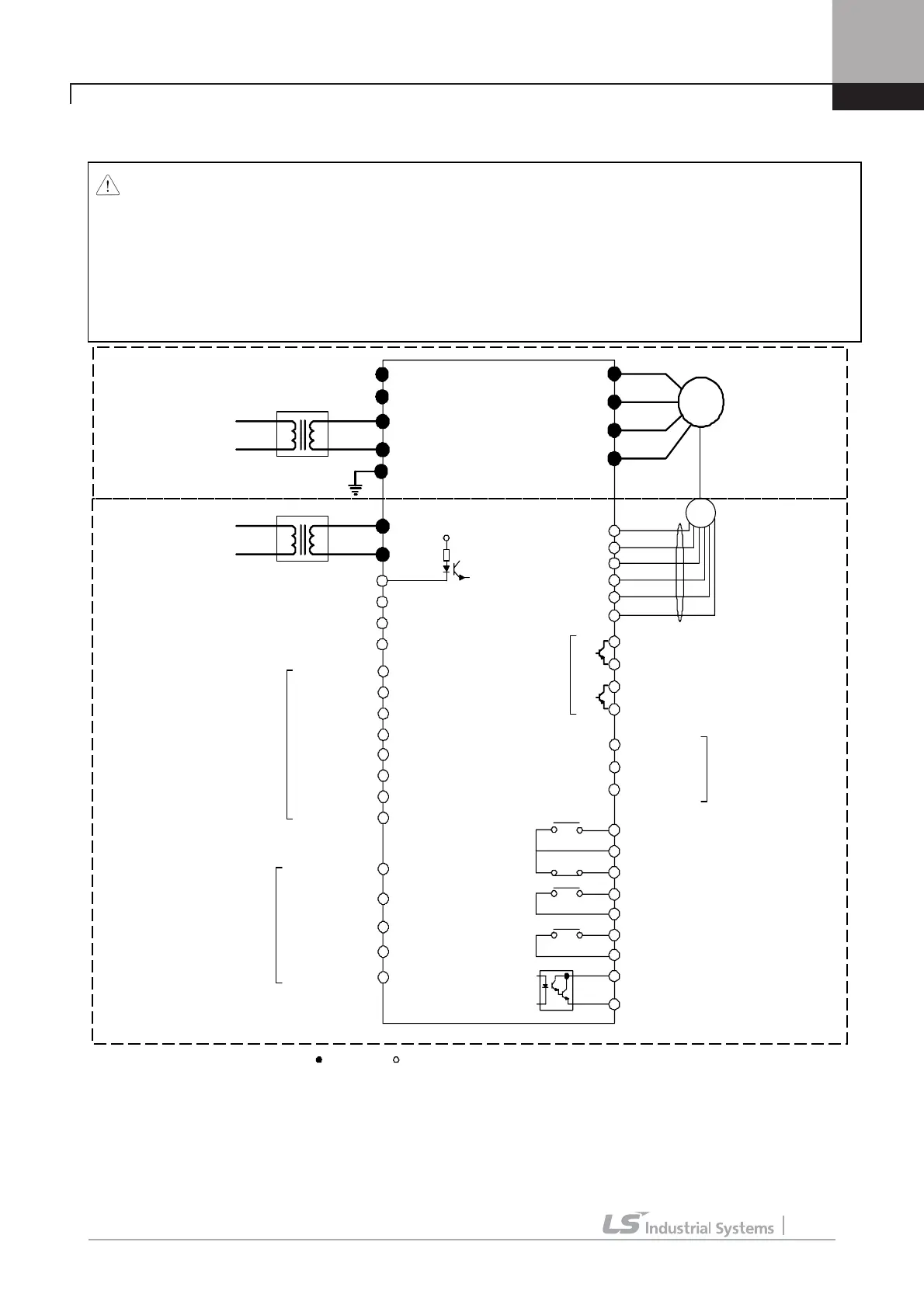
DC Power Input Type:
SV300, 370, 450, 550, 750, 900, 1100, 1320, 1600, 2200iV5-4DC
PE
P (+)
N (-)
U
V
W
FX
P1 (MM0)
P2 (MM1)
P3 (ATO)
CM
VREF
AI 1
5G
IM
GE
A+
RA
GE
RB
E
GE
Multi-function input 1
Multi-function input 2
Multi-function input 3
Common
Potentiometer
10 k ohm , 1/2W
Multi-function input
G
Encoder A
Phase input
Note ) :
Main circuit , : Control circuit
Shield
P4 (FHM)
P5 (BAT)
P6 (BRC)
P7 (MCC)
STARVERT - iV5
Multi- function input 4
Multi- function input 5
Multi- function input 6
Multi -function input 7
AI 2
AI 3
Power supply (+10 V)
Analog input 1
Analog input 2
Analog input 3
Common
Analog input
(10 ~ -10 V )
(- 10 ~ 1 0 V )
(0~10V)
(10 ~ 0V)
(0~20mA)
(20~0mA)
(Motor NTC /PTC)
Encoder B
Phase input
Power supply (5V)
Common (0V)
Open collector
output
AO 1
AO 2
5G
Analog output 1
Analog output 2
Common
Analog
output
(-10 ~ 10V)
(10 ~ -10V)
(0 ~ 10V)
(10 ~0V)
30 A
30 C
30 B
1A
1B
2B
2A
Fault relay output
( ~ AC 250V, 1A)
( ~ DC 30 V, 1A)
Auxiliary relay
output
( ~ AC 250V, 1A)
( ~ DC 30 V, 1A)
Open collector
output
(24V,50mA)
OC1
EG
B+
A-
B-
A phase encoder pulse output
B phase encoder pulse output
Encoder output Common
Encoder output Common
AC1
AC2
Aux. power source
for control circuit
Insulated
Trasformer
Note 1)
RX
BX
RST
FWD run /stop command
REV run /stop command
Emergency stop
Fault reset
24 V
(50/60Hz)(220V)
Encoder
( Line Drive Type)
DC input
(540 ~ 680 VDC)
FAN1
FAN
2
Insulated
Trasformer
Warning
FAN and MC
Power
(50/60Hz)
(220V)
G
Note 1) It is used when inverter control circuit is energized from auxiliary power source (220 VAC) without main power
supply. Use insulated transformer to separate from main power supply. (Transformer capacity: above 100VA
recommended)
Warning) It must be energized AC220V (50/60Hz) to terminal of FAN1 and FAN2 because 30 ~ 220
kW-4DC series have a cooling fan for AC power drive and MC. If not, Trip (30~160kW: “FAN/MC PWR”,
220kW: “FAN PWR”) will be occurred. The inverter is not operated unless trip is released after AC220V
inputs. The recommended order of power input and cutoff is as shown below.
(The order of power On: 220VAC Æ P(+)/N(-) Æ Run, The opder of power Off: Stop Æ P(+)/N(-)
Æ 220
VAC)

 Loading...


