Home
Lucent Technologies
Switch
CBX 3500
Lucent Technologies CBX 3500 Installation Guide
4
of 1
of 1 rating
232 pages
Give review
Manual
Specs
To Next Page
To Next Page
To Previous Page
To Previous Page
Loading...
Beta
Draft
Conf
idential
Installing
and
Removing
Modules
Insta
lling
and
Rep
la
cing
I
OP
M
odules
CBX
500
Multiserv
ice
WAN
Switch
H
ardware
Installation
Guide
4/5/03
6-19
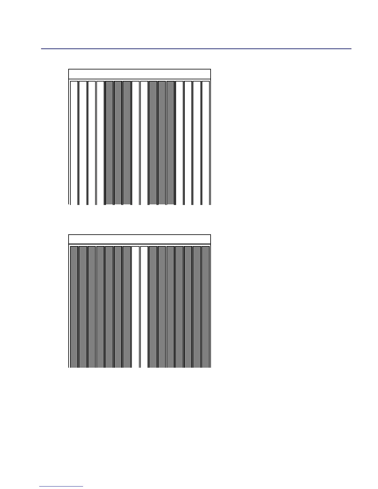
Figur
e
6-7.
IOP
Slot
s
with
SP
10
Figur
e
6-8.
IOP
Slot
s
with
SP
20,
30,
40
34
56
7
8
91
21
0
1
1
1
2
1
3
1
4
1
5
1
6
34
56
78
91
21
0
1
1
1
2
1
3
1
4
1
5
1
6
114
116
Table of Contents
Default Chapter
1
Installation Guide
1
Maintenance Agreements
5
If the Product Is Damaged
5
If Problems Arise
6
Table of Contents
7
About this Guide
21
What You Need to Know
21
Reading Path
22
Documentation for New Modules
23
How to Use this Guide
23
What's New in this Guide
24
Conventions
25
Related Documents
26
Lucent
26
Ordering Printed Manuals Online
27
Customer Comments
27
Technical Support
27
Chapter 1 Overview
29
CBX 500 Product Description
29
CBX 500 Features
30
Hardware Component Descriptions
32
Figure 1-1. CBX 500 Switch
33
Figure 1-2. Relationship of SP and IOP Modules to Backplane
34
SP Modules
35
SP Features
35
SP Redundancy
35
IOP Modules (Iops)
36
Table 1-1. Supported Redundant SP Configurations
36
I/O and SP Adapters (Ioas and Spas)
37
CBX 500 Multiservice WAN Switch Hardware Installation Guide
37
Chapter 2 Specifications and Safety Warnings
39
Electronic/Electrical Requirements
40
Table 2-1. CBX 500 Electronic/Electrical Specifications
40
Physical Specifications
41
Table 2-2. CBX 500 Physical Specifications
41
Site Specifications
42
Operating Environment
42
Space Requirements
42
Table 2-3. CBX 500 Site Specifications
42
DC Power Supply Warnings
43
Safety Warnings
43
Signes Précurseurs de Sécurité
45
Achtung: Zusätzliche Sicherheitshinweise
46
Power Cord Requirements
47
Table 2-4. AC Power Cord Requirements
47
Selecting the Installation Site
49
Checking the Switch for Damage
50
Figure 3-1. CBX 500 Switch, Typical Shipping Configuration
50
Moving the Switch to the Installation Site
51
Unpacking the Switch
51
Unpacking the Accessory Kit
52
Verifying the Hardware Configuration
53
Before Handling Equipment
53
Checking the SP and IOP Modules
53
Figure 3-2. Front View of the CBX 500
54
Checking the SPA and IOA Modules
55
Figure 3-3. CBX 500 Showing SPA and IOA Module Locations
55
Checking the PCMCIA Configuration
56
Figure 3-4. PCMCIA Card Bay
56
What's Next
57
Installing the CBX 500 Switch
59
Before You Begin
59
Required Installation Tools and Equipment
60
Setting up the Switch
61
As a Free-Standing Switch
61
As a Rack-Mounted Switch
61
Installing 19-Inch MID-Mount Brackets
62
Figure 4-1. Installing 19-Inch MID-Mount Brackets
62
Installing 23-Inch MID-Mount Brackets
63
Figure 4-2. Installing 23-Inch MID-Mount Brackets
63
Installing 23-Inch Front-Mount Brackets
64
Figure 4-3. Installing 23-Inch Front-Mount Brackets
64
Installing the Switch into the Cabinet
66
Connecting Cables to the Switch
67
Network Management Connections
67
Figure 4-4. CBX 500 Switch Connected to NMS and Console Terminal
67
Chapter 3 Preparing for the Installation
49
Connecting the Console
68
Figure 4-5. Console Connection to CBX 500 Switch
68
Setting up the NMS
69
Connecting the NMS
69
Figure 4-6. Direct Ethernet Method
70
Figure 4-7. Indirect Ethernet Method
70
Figure 4-8. Management VC/PVC Method
71
Figure 4-9. Direct Ethernet Connection
71
Using Direct Ethernet
71
Figure 4-10. Indirect Ethernet Connection
72
Using Indirect Ethernet
72
Figure 4-11. Management VC/PVC Connection
73
Using Management VC/PVC
73
Connecting External Clock Inputs and Outputs
74
T1 Clock Connection
74
E1 Clock Connection
75
Figure 4-12. External Clock Inputs and Clock Outputs
75
Connecting External T1 Clock Source Inputs/Outputs
76
Connecting Alarm Relays
77
Connecting a Remote Alarm
78
Figure 4-13. Remote Alarm Terminals
78
G.703 Product Attachment Information
79
Table 4-1. Cable Specifications
79
Determining the Operating Status
81
Before You Begin
81
Status Leds
82
Switch Status Leds
82
Table 5-1. Switch Status Leds on SP Module
82
Module Status Leds
83
Port Alarm Leds
83
Table 5-2. Module Status Leds
83
Table 5-3. Port Alarm Leds
83
Redundancy Status Leds
84
Figure 5-1. Redundancy Status Leds
84
Table 5-4. IOP LED "Boot" States
84
PCMCIA Status Leds
85
Figure 5-2. PCMCIA Status Leds
85
Power Supply Status Leds
86
DC Power Failures - LED Status
86
Table 5-5. AC/DC Power-Supply Leds
86
Table 5-6. DC Power Failures - LED Status
86
Evaluating Power Loads for a Two-Power Supply Switch
87
Calculating Power Consumption
87
Table 5-7. Power Consumption by CBX 500 Components
88
Connecting Power to the Switch
89
Switches with AC Power Supplies
89
Figure 5-3. Connecting an AC Power Supply
90
Switches with DC Power Supplies
91
Figure 5-4. Connecting the -48 VDC Power Supplies
91
Powering up the Switch
94
What's Next
95
Installing and Removing Modules
97
Installation and Removal Precautions
98
Parts Repair
98
Static Protection
98
Electrical Energy Hazard
98
Switch Processor Module
99
CBX 500 Multiservice WAN Switch Hardware Installation Guide 4/5/03Ix
99
Removing an SP Module
99
Figure 6-1. Removing a Switch Processor (SP) Module
99
Installing an SP Module
101
Figure 6-2. Installing an SP Module
101
Installing a Redundant SP
102
Replacing the SPA Module
104
Figure 6-3. Removing the SPA Module
105
Figure 6-4. PCMCIA Card Bay
106
Removing and Replacing PCMCIA Cards
108
Figure 6-5. PCMCIA Card Slot Configuration
109
Installing or Replacing IOA Modules
110
Figure 6-6. Removing IOA Modules
111
Installing IOA Modules
112
Replacing IOA Modules
113
Installing and Replacing IOP Modules
114
IOP Slots According to SP Model Number
114
Figure 6-7. IOP Slots with SP 10
115
Redundant IOP Modules
116
Figure 6-9. Redundant-Pair Slots
116
Installing a New IOP Module
117
Installing a New IOA Module
117
Installing a New IOP Module
118
Replacing an IOP Module
119
Figure 6-10. Removing IOP Modules
119
Installing or Replacing Power Supplies
121
Figure 6-11. Power Distribution Unit for the AC Power Supply
122
Figure 6-12. Power Distribution Unit for a -48 VDC Power Supply
123
Removing a Power Supply
124
Installing a Power Supply
125
Figure 6-15. Connecting the -48 VDC Power Supply
127
Replacing the Cooling Fan Module
129
Removing the Cooling Fan Module
130
Installing the Cooling Fan Module
131
Installing or Replacing Air Filters
132
Figure 6-19. Installing or Replacing the Top Air Filter
133
Chapter 7 Troubleshooting
135
Power-Up Diagnostics for SP and IOP Modules
136
Table 7-1. DIP Switch Settings
136
Switch Troubleshooting
137
Table 7-2. Switch Troubleshooting
137
IOP Module Troubleshooting
138
Table 7-3. IOP Module Status
138
Power Supply Troubleshooting
139
Table 7-4. Power Supply Status
139
Appendix A IOP and IOA Module Specifications
142
8-Port T1 and E1 IOP Modules
142
Specifications
142
Physical Dimensions
142
Power Requirements
142
Agency Approvals
142
Table A-1. 8-Port T1 and E1 IOP/IOA Physical Dimensions
142
Temperature Range
143
Physical Interfaces
143
Physical Connectors (T1
143
Status Indicators
144
Port Alarm Indicators
144
Figure A-1. T1/E1 IOP and IOA Modules
145
32-Port Channelized T1/E1 FR/IP IOM
146
Specifications
146
Physical Dimensions
146
Temperature Range
146
Agency Approvals
146
Interface Standards
147
Other Standards
147
Physical Interfaces
147
Physical Connectors
147
Cable Requirements
148
Framing
148
Clocking Options
148
Module LED Status
149
Table A-2. Module LED Status Indicators
149
Table A-3. Port Alarm Status Indicators
149
Figure A-2. 32-Port Channelized T1/E1 FR/IP IOP and IOA Modules
150
8-Port DS3 and E3 ATM UNI IOP Modules
151
Specifications
151
Physical Dimensions
151
Power Requirements
151
Table A-4. 8-Port DS3 and E3 ATM UNI IOP/IOA Physical Dimensions
151
Temperature Range
152
Agency Approvals
152
Interface Standards
152
Other Standards Supported - DS3
152
Other Standards Supported - E3
153
Physical Interfaces - DS3
153
Physical Interfaces - E3
153
Module Status Indicators
153
Port Alarm Indicators
154
Figure A-3. DS3/E3 IOP and IOA Modules
155
6-Port DS3 Frame/Ip IOP Module
156
Specifications
156
Physical Dimensions
156
Table A-5. 6-Port DS3 Frame/Ip IOP/IOA Physical Dimensions
156
Power Requirements
157
Temperature Range
157
Agency Approvals
157
Interface Standards
157
Other Standards
157
Physical Interfaces
157
Physical Connectors
157
Module Status Indicators
158
Port Alarm Indicators
158
Figure A-4. 6-Port DS3 Frame/Ip IOP and IOA Modules
159
4-Port Channelized DS3 Frame/Ip IOP Module
160
Specifications
160
Physical Dimensions
160
Power Requirements
160
Table A-6. 4-Port Channelized DS3 Frame/Ip IOP/IOA Physical Dimensions
160
Agency Approvals and Electromagnetic Emissions Certifications
161
Physical Interfaces
161
Physical Connectors
161
Interface Standards
161
Line Coding
162
Framing
162
Signal Levels
162
Table A-7. DS3 and DS1 Standards
162
Status Indicators
163
Table A-8. Module LED Status Indicators
163
Table A-9. Physical Port Status Indicators
163
Figure A-5. 4-Port Channelized DS3 Frame/Ip IOP and IOA Modules
164
4-Port ATM UNI OC-3C/Stm-1 IOP Module
165
Specifications
165
Physical Dimensions
165
Power Requirements
165
Table A-10. 4-Port ATM UNI Oc03C/Stm-1 IOP/IOA Physical Dimensions
165
Table A-11. Cable Specifications
167
Other OC-3C Standards
168
Figure A-6. OC-3C/Stm-1 IOP and IOA Modules
170
1-Port OC-12C/Stm-4 IOP Module
171
Specifications
171
Physical Dimensions
171
Power Requirements
171
Agency Approvals
171
Table A-12. 1-Port OC-12C/Stm-4 IOP/IOA Physical Dimensions
171
Temperature Range
172
Physical Interfaces
172
Signal Distance/Levels (Single-Mode Laser Optics
172
Nebs
172
Interface Standards
173
Other STM-4 Standards
173
Status Indicators
174
Port Alarm Indicators
174
Figure A-7. OC-12C/Stm-4 IOP and IOA Modules
175
4-Port Ethernet IOP Module
176
Specifications
176
Physical Dimensions
176
Power Requirements
176
Temperature Range
176
Table A-13. 4-Port Ethernet IOP/IOA Physical Dimensions
176
Physical Interfaces
177
Interface Standards
177
Management Standards
177
Nebs
177
Agency Approvals
177
Port Alarm Indicators
178
Figure A-8. 4-Port Ethernet IOP and IOA Modules
179
8-Port Subrate Module
180
Specifications
180
Physical Dimensions
180
Power Requirements
180
Temperature Range
180
Agency Approvals Electromagnetic Emissions Certifications
180
Interface Standards
181
Other Standards
181
Physical Interfaces
181
Physical Connectors
181
Line Coding
181
Framing
181
Signal Levels
181
Link Performance Monitoring
182
Miscellaneous Link Message Support
182
Module Status Indicators
182
Table A-14. Module LED Status Indicators
182
Clocking Options
182
Port Alarm Indicators
183
Table A-15. Port Alarm Status Indicators
183
Figure A-9. 8-Port Subrate DS3 FR/IP IOM Front and Back Panel
184
3-Port Channelized Inverse Multiplexing over ATM (IMA) Module
185
Specifications
185
Power Requirements
185
Temperature Range
185
Agency Approvals Electromagnetic Emissions Certifications
186
Interface Standards
186
DS1 Standards
187
Physical Interfaces
187
Line Coding
187
Signal Levels
187
Clocking Options
187
Link Performance Monitoring
188
Module LED Status
188
Port Alarm Status
188
Table A-16. Module LED Status Indicators
188
Figure A-10. 3-Port Channelized DS3/1 IMA IOM IOP and IOA Panel
189
Appendix B Cables and Pinout Assignments
191
RS-232 Shielded Null-Modem Cable
192
Figure B-1. RS-232 Shielded Null-Modem Cable
193
RS-232 Shielded Straight-Through Modem Cable
194
Figure B-2. RS-232 Shielded Straight-Through Modem Cable
195
RS-232 DB-9 to DB-25 Shielded Crossover Cable
196
Figure B-3. RS-232 DB-9 to DB-25 Shielded Crossover Cable
197
T1 Straight-Through Cable
198
T1 Crossover Cable
199
Media Independent Interface (MII
200
Appendix C Regulatory Information
203
Regulatory Standards Compliance (Pending
204
Canadian IC CS-03 Requirements
205
Avis D'industrie Canada
206
FCC Part 68 General Information
207
FCC and Telephone Company Procedures and Requirements
209
Radio Frequency Interference
209
VCCI Statement
210
BSMI Statement
210
If Problems Arise
211
Example Affidavit (United States
212
Figure D-1. Slot Assignments for IOM Redundancy
214
Appendix D Redundancy
215
SP Redundancy
215
Status Indicators
216
Redundancy Manager
217
Keep-Alive Monitoring
218
Checksum/Version Number Exchange
219
Tftp Support
219
NMS Support
220
Other manuals for Lucent Technologies CBX 3500
Configuration Guide
888 pages
4
Based on 1 rating
Ask a question
Give review
Questions and Answers:
Need help?
Do you have a question about the Lucent Technologies CBX 3500 and is the answer not in the manual?
Ask a question
Lucent Technologies CBX 3500 Specifications
General
Brand
Lucent Technologies
Model
CBX 3500
Category
Switch
Language
English
Related product manuals
Lucent Technologies CBX 500
888 pages
Lucent Technologies 5ESS
552 pages
 Loading...

