Beta Draft Confidential
Redundancy
SP Redundancy
CBX 500 Multiservice WAN Switch Hardware Installation Guide 4/5/03D-3
SP Redundancy
The CBX 500’s switch processor (SP) module is available as a fully redundant pair of
modules for high-reliability networking requirements. Redundancy is achieved by
installing two identically configured SP modules of the same model type into the
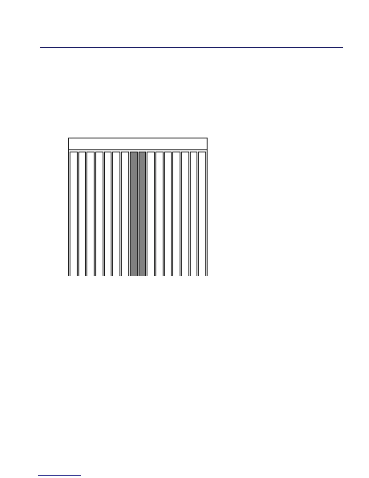
switch. They must be placed in Slots 1 and 2 and share the SPA module. The SPA
presents a single interface to the network.
Figure D-2. SP Slots in a CBX 500 Switch
The SP module configured as the redundant partner (standby), continually polls the
active SP module for its operational status. If the redundant module detects a failure in
the active module, the redundant module automatically takes over to reduce service
disruptions.
CBX 500 redundancy and recovery consists of both hardware and software
mechanisms that enable the switch to continue operation after certain types of failure.
The other module that currently supports redundancy is the power supply.
For installation instructions, see Chapter 6, “Installing and Removing Modules.”
34 56 78 91 210111213141516
 Loading...

