Beta Draft Confidential
Installing and Removing Modules
Installing or Replacing Power Supplies
CBX 500 Multiservice WAN Switch Hardware Installation Guide 4/5/036-31
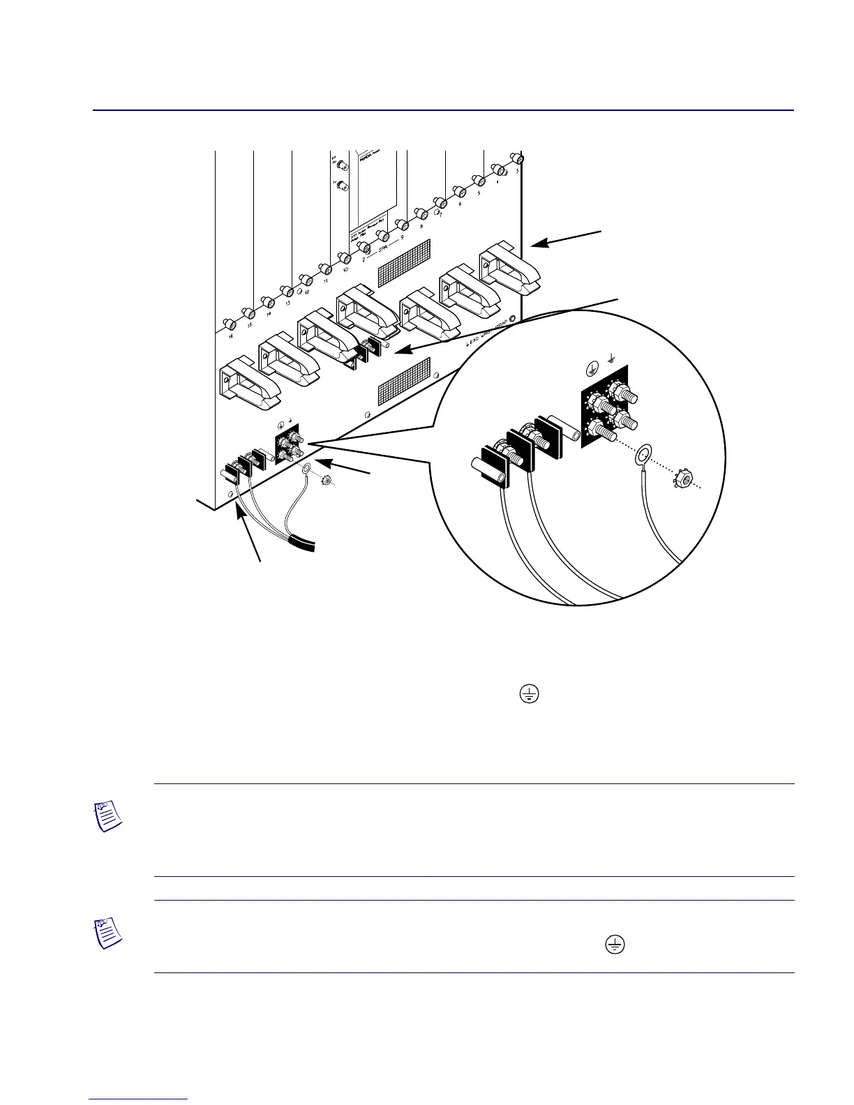
Figure 6-15. Connecting the -48 VDC Power Supply
d. Using a 7/16-in. wrench or socket, remove the top locking nut from each of
the three studs (labelled -48V, RTN, and ). Do not remove the bottom
locking nut.
e. Install the three ring lugs onto the appropriate posts.
POWER FEED B
–48VDC
RTN
POWER FEED B
–48VDC
RTN
POWER FEED A
–48VDC
RTN
Secondary Power Supply
Connectors
Ground
Cable Strain Relief Clamps
Primary Power Supply
Connectors
Note – You can optionally ground the chassis to the enclosure by attaching a dual
mount ground lug to the dual mount ground on the back of the unit (see Figure 5-4 in
Chapter 5).
Note – It is recommended that, to provide a single-point ground connection, only one
of the chassis grounds should be connected to earth ground ( ).
 Loading...

